Jeep Grand Cherokee WK (2022 year). Manual in english - page 12
 

  Index      Manuals     Jeep Grand Cherokee WK (2022 year). Manual in english


Search            copyright infringement  


Content      ..     10      11      12      13     ..


Jeep Grand Cherokee WK (2022 year). Manual in english - page 12


186

MULTIMEDIA


A

CCESSORY

 G

AUGES

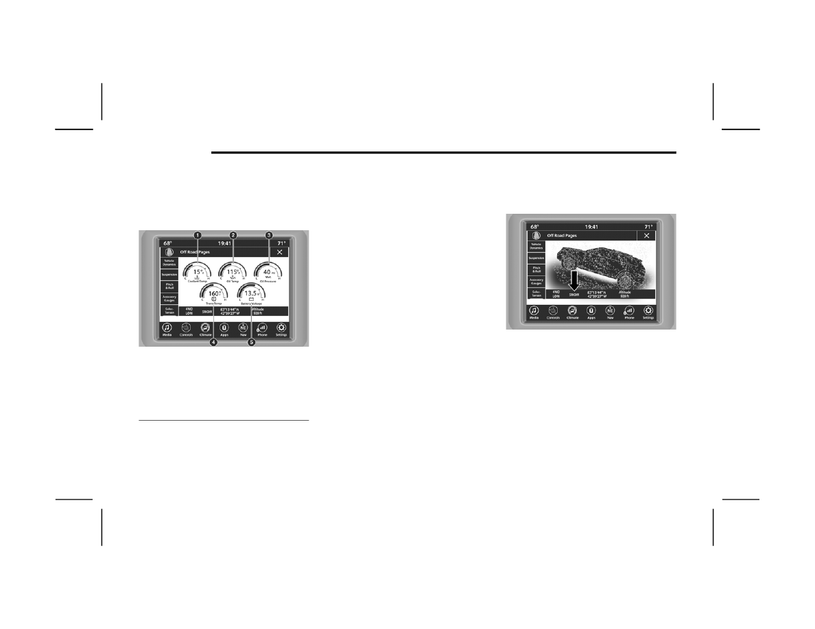
The Accessory Gauges page displays the current 

status of the vehicle’s Coolant Temperature, Oil 

Temperature, Oil Pressure (Gas Vehicles Only), 

Transmission Temperature, and Battery Voltage.

Accessory Gauges Menu

S

ELEC

-T

ERRAIN

 — I

F

 E

QUIPPED

The Selec-Terrain page displays the current 

Selec-Terrain mode through a high resolution 

image. Adjusting the Selec-Terrain mode will alter 

the image on the screen. The vehicle must be in 

the ON/RUN position to display Selec-Terrain 

information.
The selectable modes are as follows:

Auto — Default

Snow

Sand

Mud

Rock — Vehicle Must Be In 4WD LOW

NOTE:

While in the Selec-Terrain pages, the Off-Road 

Pages Status Bar will also display the current 

Selec-Terrain mode.

Current Selec-Terrain Mode

1 — Coolant Temperature
2 — Oil Temperature
3 — Oil Pressure (Gas Vehicles Only)
4 — Transmission Temperature
5 — Battery Voltage

187

(Continued)

SAFETY

SAFETY FEATURES

A

NTI

-L

OCK

 B

RAKE

 S

YSTEM

 (ABS) 

The ABS provides increased vehicle stability and 

brake performance under most braking conditions. 

The system automatically prevents wheel lock and 

enhances vehicle control during braking.
The ABS performs a self-check cycle to ensure that 

the ABS is working properly each time the vehicle 

is started and driven. During this self-check, you 

may hear a slight clicking sound, as well as some 

related motor noises.
The ABS is activated during braking when the 

system detects one or more wheels are beginning 

to lock. Road conditions such as ice, snow, gravel, 

bumps, railroad tracks, loose debris, or panic stops 

may increase the likelihood of ABS activation(s).
You also may experience the following normal 

characteristics when the ABS activates:

ABS motor noise or clicking sounds (you may 

continue to hear for a short time after the stop)

Brake pedal pulsations

A slight drop of the brake pedal at the end of the 

stop

The ABS is designed to function with the Original 

Equipment Manufacturer (OEM) tires. Modification 

may result in degraded ABS performance.

Anti-Lock Brake System (ABS) Warning 

Light

The yellow ABS Warning Light will turn on when the 

ignition is placed in the ON/RUN mode and may 

stay on for as long as four seconds.
If the ABS Warning Light remains on or comes on 

while driving, it indicates that the Anti-Lock portion 

of the brake system is not functioning and that 

service is required. However, the conventional 

brake system will continue to operate normally if 

the ABS Warning Light is on.

WARNING!

The ABS contains sophisticated electronic 

equipment that may be susceptible to interfer

-

ence caused by improperly installed or high 

output radio transmitting equipment. This 

interference can cause possible loss of 

anti-lock braking capability. Installation of 

such equipment should be performed by qual

-

ified professionals.

Pumping of the Anti-Lock Brakes will diminish 

their effectiveness and may lead to a collision. 

Pumping makes the stopping distance longer. 

Just press firmly on your brake pedal when you 

need to slow down or stop.

The ABS cannot prevent the natural laws of 

physics from acting on the vehicle, nor can it 

increase braking or steering efficiency beyond 

that afforded by the condition of the vehicle 

brakes and tires or the traction afforded.

The ABS cannot prevent collisions, including 

those resulting from excessive speed in turns, 

following another vehicle too closely, or hydro

-

planing.

The capabilities of an ABS equipped vehicle 

must never be exploited in a reckless or 

dangerous manner that could jeopardize the 

user’s safety or the safety of others.

WARNING!

6

188

SAFETY


If the ABS Warning Light is on, the brake system 

should be serviced as soon as possible to restore 

the benefits of Anti-Lock Brakes. If the ABS 

Warning Light does not come on when the ignition 

is placed in the ON/RUN mode, have the light 

repaired as soon as possible.

E

LECTRONIC

 B

RAKE

 C

ONTROL

 (EBC) 

S

YSTEM


Your vehicle is equipped with an advanced 

Electronic Brake Control (EBC) system. This system 

includes Anti-Lock Brake System (ABS), Brake 

Assist System (BAS), Electronic Brake Force 

Distribution (EBD), Electronic Roll Mitigation 

(ERM), Electronic Stability Control (ESC), Hill Start 

Assist (HSA), and Traction Control System (TCS). 

These systems work together to enhance both 

vehicle stability and control in various driving 

conditions.
Your vehicle may also be equipped with Dynamic 

Steering Torque (DST), Hill Descent Control (HDC), 

Ready Alert Braking (RAB), Rain Brake Support 

(RBS), Selec-Speed Control (SSC) and Trailer Sway 

Control (TSC).

Brake System Warning Light

The red Brake System Warning Light will turn on 

when the ignition is placed in the ON/RUN mode 

and may stay on for as long as four seconds.
If the Brake System Warning Light remains on or 

comes on while driving, it indicates that the brake 

system is not functioning properly and that 

immediate service is required. If the Brake System 

Warning Light does not come on when the ignition 

is placed in the ON/RUN mode, have the light 

repaired as soon as possible.

Brake Assist System (BAS) 

The BAS is designed to optimize the vehicle’s 

braking capability during emergency braking 

maneuvers. The system detects an emergency 

braking situation by sensing the rate and amount 

of brake application and then applies optimum 

pressure to the brakes. This can help reduce 

braking distances. The BAS complements the 

Anti-Lock Brake System (ABS). Applying the brakes 

very quickly results in the best BAS assistance. To 

receive the benefit of the system, you must apply 

continuous braking pressure during the stopping 

sequence (do not “pump” the brakes). Do not 

reduce brake pedal pressure unless braking is no 

longer desired. Once the brake pedal is released, 

the BAS is deactivated.

Dynamic Steering Torque (DST)

DST is a feature of the Electronic Stability Control 

(ESC) and Electric Power Steering (EPS) modules 

that provides torque at the steering wheel for 

certain driving conditions in which the ESC module 

is detecting vehicle instability. The torque that the 

steering wheel receives is only meant to help the 

driver realize optimal steering behavior in order to 

reach/maintain vehicle stability. The only 

notification the driver receives that the feature is 

active is the torque applied to the steering wheel.

WARNING!

The Brake Assist System (BAS) cannot prevent 

the natural laws of physics from acting on the 

vehicle, nor can it increase the traction afforded 

by prevailing road conditions. BAS cannot 

prevent collisions, including those resulting from 

excessive speed in turns, driving on very slippery 

surfaces, or hydroplaning. The capabilities of a 

BAS-equipped vehicle must never be exploited in 

a reckless or dangerous manner, which could 

jeopardize the user's safety or the safety of 

others.

SAFETY

189

NOTE:

The DST feature is only meant to help the driver 

realize the correct course of action through small 

torques on the steering wheel, which means the 

effectiveness of the DST feature is highly 

dependent on the driver’s sensitivity and overall 

reaction to the applied torque. It is very important 

to realize that this feature will not steer the vehicle, 

meaning the driver is still responsible for steering 

the vehicle.

Electronic Brake Force Distribution (EBD)

EBD function manages the distribution of the 

braking torque between the front and rear axles by 

limiting braking pressure to the rear axle. This is 

done to prevent overslip of the rear wheels to avoid 

vehicle instability, and to prevent the rear axle from 

entering ABS before the front axle.

Electronic Roll Mitigation (ERM) 

ERM anticipates the potential for wheel lift by 

monitoring the driver’s steering wheel input and 

the speed of the vehicle. When ERM determines 

that the rate of change of the steering wheel angle 

and vehicle’s speed are sufficient to potentially 

cause wheel lift, it then applies the appropriate 

brake and may also reduce engine power to lessen 

the chance that wheel lift will occur. ERM can only 

reduce the chance of wheel lift occurring during 

severe or evasive driving maneuvers; it cannot 

prevent wheel lift due to other factors, such as 

road conditions, leaving the roadway, or striking 

objects or other vehicles.

NOTE:

ERM is disabled any time the ESC is in “Full Off” 

mode (if equipped). See  

Ú

page 189 for a 

complete explanation of the available ESC modes.

Electronic Stability Control (ESC) 

ESC enhances directional control and stability of 

the vehicle under various driving conditions. ESC 

corrects for oversteering or understeering of the 

vehicle by applying the brake of the appropriate 

wheel(s) to counteract the above conditions. 

Engine power may also be reduced to help the 

vehicle maintain the desired path.

Oversteer — when the vehicle is turning more 

than appropriate for the steering wheel position.

Understeer — when the vehicle is turning less 

than appropriate for the steering wheel position.

ESC uses sensors in the vehicle to determine the 

vehicle path intended by the driver and compares 

it to the actual path of the vehicle. When the actual 

path does not match the intended path, ESC 

applies the brake of the appropriate wheel to 

assist in counteracting the oversteer or understeer 

condition.
The ESC Activation/Malfunction Indicator Light 

located in the instrument cluster will start to flash 

as soon as the ESC system becomes active. The 

ESC Activation/Malfunction Indicator Light also 

flashes when the Traction Control System (TCS) is 

active. If the ESC Activation/Malfunction Indicator 

Light begins to flash during acceleration, ease up 

on the accelerator and apply as little throttle as 

possible. Be sure to adapt your speed and driving 

to the prevailing road conditions.

WARNING!

Many factors, such as vehicle loading, road 

conditions and driving conditions, influence the 

chance that wheel lift or rollover may occur. ERM 

cannot prevent all wheel lift or rollovers, 

especially those that involve leaving the roadway 

or striking objects or other vehicles. The 

capabilities of an ERM-equipped vehicle must 

never be exploited in a reckless or dangerous 

manner which could jeopardize the user's safety 

or the safety of others.

6

190

SAFETY


(Continued)

ESC Operating Modes

Depending upon model and mode of operation, the 

ESC system may have multiple operating modes.
ESC On
This is the normal operating mode for the ESC. 

Whenever the vehicle is started, the ESC system 

will be in this mode. This mode should be used for 

most driving conditions. Alternate ESC modes 

should only be used for specific reasons as noted 

in the following paragraphs.

Partial Off
This mode may be useful if the vehicle becomes 

stuck. This mode may modify TCS and ESC 

thresholds for activation, which allows for more 

wheel spin than normally allowed.
To enter the “Partial Off” mode, momentarily push 

the ESC OFF switch and the ESC OFF Indicator 

Light will illuminate. To turn the ESC on again, 

momentarily push the ESC OFF switch and the ESC 

OFF Indicator Light will turn off.

NOTE:

For vehicles with multiple partial ESC modes, the 

push and release of the button will toggle the ESC 

modes. Multiple attempts may be required to 

return to “ESC On”.

WARNING!

Electronic Stability Control (ESC) cannot 

prevent the natural laws of physics from 

acting on the vehicle, nor can it increase the 

traction afforded by prevailing road condi

-

tions. ESC cannot prevent accidents, including 

those resulting from excessive speed in turns, 

driving on very slippery surfaces, or hydro

-

planing. ESC also cannot prevent accidents 

resulting from loss of vehicle control due to 

inappropriate driver input for the conditions. 

Only a safe, attentive, and skillful driver can 

prevent accidents. The capabilities of an ESC 

equipped vehicle must never be exploited in a 

reckless or dangerous manner which could 

jeopardize the user’s safety or the safety of 

others.

Vehicle modifications, or failure to properly 

maintain your vehicle, may change the 

handling characteristics of your vehicle, and 

may negatively affect the performance of the 

ESC system. Changes to the steering system, 

suspension, braking system, tire type and size 

or wheel size may adversely affect ESC perfor

-

mance. Improperly inflated and unevenly worn 

tires may also degrade ESC performance. Any 

vehicle modification or poor vehicle mainte

-

nance that reduces the effectiveness of the 

ESC system can increase the risk of loss of 

vehicle control, vehicle rollover, personal 

injury and death.

WARNING!

WARNING!

When in “Partial Off” mode, the TCS function

-

ality of ESC, except for the limited slip feature 

described in the TCS section, has been 

disabled and the ESC OFF Indicator Light will 

be illuminated. When in “Partial Off” mode, 

the engine power reduction feature of TCS is 

disabled, and the enhanced vehicle stability 

offered by the ESC system is reduced.

Trailer Sway Control (TSC) is disabled when 

the ESC system is in the “Partial Off” mode.

SAFETY

191

ESC Activation/Malfunction Indicator Light 

And ESC OFF Indicator Light 

The ESC Activation/Malfunction Indicator 

Light in the instrument cluster will come 

on when the ignition is placed in the ON/

RUN mode. It should go out with the 

engine running. If the ESC Activation/Malfunction 

Indicator Light comes on continuously with the 

engine running, a malfunction has been detected 

in the ESC system. If this light remains on after 

several ignition cycles, and the vehicle has been 

driven several miles (kilometers) at speeds greater 

than 30 mph (48 km/h), see an authorized dealer 

as soon as possible to have the problem 

diagnosed and corrected.
The ESC Activation/Malfunction Indicator Light 

starts to flash as soon as the tires lose traction and 

the ESC system becomes active. The ESC 

Activation/Malfunction Indicator Light also flashes 

when TCS is active. If the ESC Activation/

Malfunction Indicator Light begins to flash during 

acceleration, ease up on the accelerator and apply 

as little throttle as possible. Be sure to adapt your 

speed and driving to the prevailing road conditions.

The ESC OFF Indicator Light indicates the 

customer has elected to have the 

Electronic Stability Control (ESC) in a 

reduced mode.

NOTE:

The ESC Activation/Malfunction Indicator Light 

and the ESC OFF Indicator Light come on 

momentarily each time the ignition is placed in 

the ON/RUN position.

Each time the ignition is placed in the ON/RUN 

position, the ESC system will be on even if it was 

turned off previously.

The ESC system will make buzzing or clicking 

sounds when it is active. This is normal; the 

sounds will stop when ESC becomes inactive 

following the maneuver that caused the ESC 

activation.

Hill Descent Control (HDC) — If Equipped  

HDC is intended for low speed off-road 

driving while in 4WD Low. HDC maintains 

vehicle speed while descending hills 

during various driving situations. HDC 

controls vehicle speed by actively controlling the 

brakes.
HDC Has Three States:  
1. Off (feature is not enabled and will not 

activate).

2. Enabled (feature is enabled and ready but 

activation conditions are not met, or driver is 

actively overriding with brake or throttle 

application).

3. Active (feature is enabled and actively 

controlling vehicle speed).

Enabling HDC
HDC is enabled by pushing the HDC switch, but the 

following conditions must also be met to enable 

HDC:

The driveline is in 4WD Low.

The vehicle speed is below 5 mph (8 km/h).

The parking brake is released.

The driver door is closed.

Activating HDC
Once HDC is enabled it will activate automatically 

if driven down a grade of sufficient magnitude. The 

set speed for HDC is selectable by the driver, and 

can be adjusted by using the gear shift +/-. The 

following summarizes the HDC set speeds:
HDC Target Set Speeds

P = No set speed. HDC may be enabled but will 

not activate.

R = 0.6 mph (1 km/h)

N = 1.2 mph (2 km/h)

D = 0.6 mph (1 km/h)

1st = 0.6 mph (1 km/h)

2nd = 1.2 mph (2 km/h)

3rd = 1.8 mph (3 km/h)

6

192

SAFETY


4th = 2.5 mph (4 km/h)

5th = 3.1 mph (5 km/h)

6th = 3.7 mph (6 km/h)

7th = 4.3 mph (7 km/h)

8th = 5.0 mph (8 km/h)

9th = 5.6 mph (9 km/h) – if equipped

NOTE:

During HDC the +/- shifter input is used for HDC 

target speed selection, but will not affect the gear 

chosen by the transmission. When actively 

controlling HDC the transmission will shift appro

-

priately for the driver-selected set speed and corre

-

sponding driving conditions.
Driver Override
The driver may override HDC activation with 

throttle or brake application at any time.
Deactivating HDC
HDC will be deactivated but remain available if any 

of the following conditions occur:

Driver overrides HDC set speed with throttle or 

brake application.

Vehicle speed exceeds 20 mph (32 km/h) but 

remains below 40 mph (64 km/h).

Vehicle is on a downhill grade of insufficient 

magnitude, is on level ground, or is on an uphill 

grade.

Vehicle is shifted to PARK.

Disabling HDC
HDC will be deactivated and disabled if any of the 

following conditions occur:

The driver pushes the HDC switch.

The driveline is shifted out of 4WD Low.

The parking brake is applied.

The driver door opens.

The vehicle is driven greater than 20 mph 

(32 km/h) for greater than 70 seconds.

The vehicle is driven greater than 40 mph 

(64 km/h) (HDC exits immediately).

HDC detects excessive brake temperature.

Feedback To The Driver
The instrument cluster has an HDC icon and the 

HDC switch has an LED icon, which offers feedback 

to the driver about the state HDC is in.

The cluster icon and switch lamp will illuminate 

and remain on solid when HDC is enabled or 

activated. This is the normal operating condition 

for HDC.

The cluster icon and switch lamp will flash for 

several seconds, then extinguish when the 

driver pushes the HDC switch but enable condi

-

tions are not met.

The cluster icon and switch lamp will flash for 

several seconds, then extinguish when HDC 

disables due to excess speed.

The cluster icon and switch lamp will flash when 

HDC deactivates due to overheated brakes. The 

flashing will stop and HDC will activate again 

once the brakes have cooled sufficiently.

Hill Start Assist (HSA)  

HSA is designed to mitigate roll back from a 

complete stop while on an incline. If the driver 

releases the brake while stopped on an incline, 

HSA will continue to hold the brake pressure for a 

short period. If the driver does not apply the 

throttle before this time expires, the system will 

release brake pressure and the vehicle will roll 

down the hill as normal.
The following conditions must be met in order for 

HSA to activate:

The feature must be enabled.

The vehicle must be stopped.

The parking brake must be off.

The driver door must be closed.

The vehicle must be on a sufficient grade.

WARNING!

HDC is only intended to assist the driver in 

controlling vehicle speed when descending hills. 

The driver must remain attentive to the driving 

conditions and is responsible for maintaining a 

safe vehicle speed.

SAFETY

193

The gear selection must match vehicle uphill 

direction (i.e., vehicle facing uphill is in forward 

gear; vehicle backing uphill is in REVERSE gear).

HSA will work in REVERSE gear and all forward 

gears. The system will not activate if the trans

-

mission is in PARK or NEUTRAL. For vehicles 

equipped with a manual transmission, if the 

clutch is pressed, HSA will remain active.

Disabling And Enabling HSA

This feature can be turned on or turned off. To 

change the current setting using the Uconnect 

Settings, see  

Ú

page 155.

Towing With HSA

HSA will also provide assistance to mitigate roll 

back while towing a trailer.

Rain Brake Support (RBS)

RBS may improve braking performance in wet 

conditions. It will periodically apply a small amount 

of brake pressure to remove any water buildup on 

the front brake rotors. It functions when the 

windshield wipers are in LO or HI speed. When RBS 

is active, there is no notification to the driver and 

no driver interaction is required.

Ready Alert Braking (RAB)

RAB may reduce the time required to reach full 

braking during emergency braking situations. It 

anticipates when an emergency braking situation 

may occur by monitoring how fast the throttle is 

released by the driver. The Electronic Brake 

Control (EBC) system will prepare the brake system 

for a panic stop.

Selec-Speed Control (SSC) — If Equipped

SSC is intended for off-road driving in 

4WD Low only. SSC maintains vehicle 

speed by actively controlling engine 

torque and brakes.

SSC has three states:
1. Off (feature is not enabled and will not 

activate)

2. Enabled (feature is enabled and ready but 

activation conditions are not met, or driver is 

actively overriding with brake or throttle 

application)

3. Active (feature is enabled and actively 

controlling vehicle speed)

WARNING!

There may be situations where the Hill Start 

Assist (HSA) will not activate and slight rolling 

may occur, such as on minor hills or with a 

loaded vehicle, or while pulling a trailer. HSA is 

not a substitute for active driving involvement. It 

is always the driver’s responsibility to be 

attentive to distance to other vehicles, people, 

and objects, and most importantly brake 

operation to ensure safe operation of the vehicle 

under all road conditions. Your complete 

attention is always required while driving to 

maintain safe control of your vehicle. Failure to 

follow these warnings can result in a collision or 

serious personal injury.

WARNING!

If you use a trailer brake controller with your 

trailer, the trailer brakes may be activated and 

deactivated with the brake switch. If so, there 

may not be enough brake pressure to hold 

both the vehicle and the trailer on a hill when 

the brake pedal is released. In order to avoid 

rolling down an incline while resuming accel

-

eration, manually activate the trailer brake or 

apply more vehicle brake pressure prior to 

releasing the brake pedal.

HSA is not a parking brake. Always apply the 

parking brake fully when exiting your vehicle. 

Also, be certain to place the transmission in 

PARK.

Failure to follow these warnings can result in a 

collision or serious personal injury.

6

194

SAFETY


Enabling SSC
SSC is enabled by pushing the SSC switch, but the 

following conditions must also be met to enable 

SSC:

The driveline is in 4WD Low.

The vehicle speed is below 5 mph (8 km/h).

The parking brake is released.

The driver door is closed.

The driver is not applying throttle.

Activating SSC
Once SSC is enabled it will activate automatically 

once the following conditions are met:

The driver releases the throttle.

The driver releases the brake.

The transmission is in any selection other 

than PARK.

The vehicle speed is below 20 mph (32 km/h).

The set speed for SSC is selectable by the driver, 

and can be adjusted by using the gear shift +/-. 

Additionally, the SSC set speed may be reduced 

when climbing a grade and the level of set speed 

reduction depends on the magnitude of grade. 

The following summarizes the SSC set speeds:
SSC Target Set Speeds

1st = .6 mph (1 km/h)

2nd = 1.2 mph (2 km/h)

3rd = 1.8 mph (3 km/h)

4th = 2.5 mph (4 km/h)

5th = 3.1 mph (5 km/h)

6th = 3.7 mph (6 km/h)

7th = 4.3 mph (7 km/h)

8th = 5 mph (8 km/h)

9th = 5.6 mph (9 km/h) – if equipped

REVERSE = .6 mph (1 km/h)

NEUTRAL = 1.2 mph (2 km/h)

PARK = SSC remains enabled but not active

NOTE:

During SSC the +/- shifter input is used for SSC 

target speed selection but will not affect the 

gear chosen by the transmission. While actively 

controlling SSC the transmission will shift appro

-

priately for the driver-selected set speed and 

corresponding driving conditions.

SSC operation is influenced by Off Road+ drive 

mode if active. The differences may be notable 

to the driver as a varying level of aggressive

-

ness.

Driver Override:
The driver may override SSC activation with throttle 

or brake application at any time.

Deactivating SSC
SSC will be deactivated but remain available if any 

of the following conditions occur:

Driver overrides SSC set speed with throttle or 

brake application

Vehicle speed exceeds 20 mph (32 km/h) but 

remains below 40 mph (64 km/h)

Vehicle is shifted to PARK

Disabling SSC
SSC will deactivate and be disabled if any of the 

following conditions occur:

The driver pushes the SSC switch.

The driveline is shifted out of 4WD Low.

The parking brake is applied.

The driver door opens.

The vehicle is driven greater than 20 mph 

(32 km/h) for greater than 70 seconds.

The vehicle is driven greater than 40 mph 

(64 km/h) (SSC exits immediately).

Feedback To The Driver:
The instrument cluster has an SSC icon and the 

SSC switch has an LED which offer feedback to the 

driver about the state SSC is in.

The cluster icon and switch lamp will illuminate 

and remain on solid when SSC is enabled or 

SAFETY

195

activated. This is the normal operating condition 

for SSC.

The cluster icon and switch lamp will flash for 

several seconds then extinguish when the driver 

pushes the SSC switch but enable conditions 

are not met.

The cluster icon and switch lamp will flash for 

several seconds then extinguish when SSC 

disables due to excess speed.

The cluster icon and switch lamp will flash then 

extinguish when SSC deactivates due to over

-

heated brakes.

Traction Control System (TCS) 

The TCS monitors the amount of wheel spin of 

each of the driven wheels. If wheel spin is 

detected, the TCS may apply brake pressure to the 

spinning wheel(s) and/or reduce engine power to 

provide enhanced acceleration and stability. A 

feature of the TCS, Brake Limited Differential (BLD) 

functions similarly to a limited slip differential and 

controls the wheel spin across a driven axle. If one 

wheel on a driven axle is spinning faster than the 

other, the system will apply the brake of the 

spinning wheel. This will allow more engine power 

to be applied to the wheel that is not spinning. BLD 

may remain enabled even if TCS and Electronic 

Stability Control (ESC) are in reduced modes.

Trailer Sway Control (TSC)  

TSC uses sensors in the vehicle to recognize an 

excessively swaying trailer and will take the 

appropriate actions to attempt to stop the sway.

NOTE:

TSC cannot stop all trailers from swaying. Always 

use caution when towing a trailer and follow the 

trailer tongue weight recommendations  

Ú

page 136.

When TSC is functioning, the ESC Activation/

Malfunction Indicator Light will flash, the engine 

power may be reduced and you may feel the 

brakes being applied to individual wheels to 

attempt to stop the trailer from swaying. TSC is 

disabled when the ESC system is in the “Partial 

Off” or “Full Off” modes.

AUXILIARY DRIVING SYSTEMS

B

LIND

 S

POT

 M

ONITORING

 (BSM) —

I

F

 E

QUIPPED

BSM uses two radar sensors, located inside the 

rear fascia/bumper, to detect highway licensable 

vehicles (automobiles, trucks, motorcycles, etc.) 

that enter the blind spot zones from the rear/front/

side of the vehicle.

Rear Detection Zones

When the vehicle is started, the BSM Warning light 

will momentarily illuminate in both outside 

rearview mirrors to let the driver know that the 

system is operational. The BSM system sensors 

operate when the vehicle is in any forward gear.

WARNING!

SSC is only intended to assist the driver in 

controlling vehicle speed when driving in off 

road conditions. The driver must remain 

attentive to the driving conditions and is 

responsible for maintaining a safe vehicle 

speed.

WARNING!

If TSC activates while driving, slow the vehicle 

down, stop at the nearest safe location, and 

adjust the trailer load to eliminate trailer sway.

6

196

SAFETY


The BSM detection zone covers approximately one 

lane width on both sides of the vehicle 12 ft 

(3.8 m). The zone length starts at the side of the 

vehicle, near the B-pillar, and extends 

approximately 10 ft (3 m) beyond the rear fascia/

bumper of the vehicle. The BSM system monitors 

the detection zones on both sides of the vehicle 

when the vehicle speed reaches approximately 

6 mph (10 km/h) or higher and will alert the driver 

of vehicles in these areas.

NOTE:

The BSM system DOES NOT alert the driver 

about rapidly approaching vehicles that are 

outside the detection zones.

The BSM system detection zone DOES NOT 

change if your vehicle is towing a trailer. There

-

fore, visually verify the adjacent lane is clear for 

both your vehicle and trailer before making a 

lane change. If the trailer or other object (i.e., 

bicycle, sports equipment) extends beyond the 

side of your vehicle, this may result in random 

false detections on the trailer, and false chimes 

when the turn signal is used.

The BSM system may experience drop outs 

(blinking on and off) of the side mirror warning 

indicator lamps when a motorcycle or any small 

object remains at the side of the vehicle for 

extended periods of time (more than a couple of 

seconds).

The BSM system can become blocked if snow, ice, 

mud, or other road contaminations accumulate on 

the rear fascia/bumper where the radar sensors 

are located. The system may also detect blockage 

if the vehicle is operated in areas with extremely 

low radar returns such as a desert or parallel to a 

large elevation drop. If blockage is detected, a 

“Blind Spot Temporarily Unavailable, Wipe Rear 

Corners” message will display in the cluster, both 

mirror lights will illuminate, and BSM and RCP 

alerts will not occur. This is normal operation. The 

system will automatically recover and resume 

function when the condition clears. To minimize 

system blockage, do not block the area of the rear 

fascia/bumper where the radar sensors are 

located with foreign objects (bumper stickers, 

bicycle racks, etc.) and keep it clear of road 

contaminations.

Sensor Location

The BSM system notifies the driver of objects in the 

detection zones by illuminating the BSM warning 

light located in the outside mirrors. In addition, 

when the turn signal is activated during the alert on 

the side of the vehicle corresponding to the alert, 

an audible (chime) alert can be heard. During this 

audible (chime) alert, the radio volume will be 

reduced. See  

Ú

page 199 in this section for 

further information.

Warning Light Location

The BSM system monitors the detection zone from 

three different entry points (side, rear, front) while 

driving to see if an alert is necessary. The BSM 

system will issue an alert during these types of 

zone entries.

SAFETY

197

Entering From The Side
Vehicles that move into your adjacent lanes from 

either side of the vehicle.

Side Monitoring

Entering From The Rear
Vehicles that come up from behind your vehicle on 

either side and enter the rear detection zone with 

a relative speed of less than 30 mph (48 km/h).

Rear Monitoring

Overtaking Traffic
If you pass another vehicle slowly with a relative 

speed less than 15 mph (24 km/h) and the vehicle 

remains in the blind spot for approximately

1.5 seconds, the warning light will be illuminated. 

If the difference in speed between the two vehicles 

is greater than 15 mph (24 km/h), the warning 

light will not illuminate.

Overtaking/Approaching

Overtaking/Passing

The BSM system is designed not to issue an alert 

on stationary objects such as guardrails, posts, 

walls, foliage, berms, etc. However, occasionally 

the system may alert on such objects. This is 

normal operation and your vehicle does not require 

service.

6

198

SAFETY


The BSM system will not alert you of objects that 

are traveling in the opposite direction of the vehicle 

in adjacent lanes  

Ú

page 321.

Opposing Traffic

Rear Cross Path (RCP)

RCP is a feature that is intended to aid the driver 

when backing out of parking spaces where their 

vision of oncoming vehicles may be blocked. 

Proceed slowly and cautiously out of the parking 

space until the rear end of the vehicle is exposed. 

The RCP system will then have a clear view of the 

cross traffic and if an oncoming vehicle is 

detected, alert the driver.

RCP Detection Zones

RCP monitors the rear detection zones on both 

sides of the vehicle, for objects that are moving 

toward the side of the vehicle with a minimum 

speed of approximately 5 mph (8 km/h), to objects 

moving a maximum of approximately 20 mph 

(32 km/h), such as in parking lot situations.

NOTE:

In a parking lot situation, oncoming vehicles can be 

blocked by vehicles parked on either side. If the 

sensors are blocked by other structures or 

vehicles, the system will not be able to alert the 

driver. 
When RCP is on and the vehicle is in REVERSE (R), 

the driver is alerted using both the visual and 

audible alarms, including reducing the radio 

volume.

WARNING!

The Blind Spot Monitoring system is only an aid 

to help detect objects in the blind spot zones. 

The BSM system is not designed to detect 

pedestrians, bicyclists, or animals. Even if your 

vehicle is equipped with the BSM system, always 

check your vehicle’s mirrors, glance over your 

shoulder, and use your turn signal before 

changing lanes. Failure to do so can result in 

serious injury or death.

WARNING!

Rear Cross Path Detection (RCP) is not a backup 

aid system. It is intended to be used to help a 

driver detect an oncoming vehicle in a parking 

lot situation. Drivers must be careful when 

backing up, even when using RCP. Always check 

carefully behind your vehicle, look behind you, 

and be sure to check for pedestrians, animals, 

other vehicles, obstructions, and blind spots 

before backing up. Failure to do so can result in 

serious injury or death.

SAFETY

199

Blind Spot Modes

Blind Spot has three selectable modes of 

operation that are available in the Uconnect 

system.
Blind Spot Alert Lights Only
When operating in Blind Spot Alert mode, the BSM 

system will provide a visual alert in the appropriate 

side view mirror based on a detected object. 

However, when the system is operating in Rear 

Cross Path (RCP) mode, the system will respond 

with both visual and audible alerts when a 

detected object is present. Whenever an audible 

alert is requested, the radio is muted.
Blind Spot Alert Lights/Chime
When operating in Blind Spot Alert Lights/Chime 

mode, the BSM system will provide a visual alert in 

the appropriate side view mirror based on a 

detected object. If the turn signal is then activated, 

and it corresponds to an alert present on that side 

of the vehicle, an audible chime will also be 

sounded. Whenever a turn signal and detected 

object are present on the same side at the same 

time, both the visual and audible alerts will be 

issued. In addition to the audible alert the radio 

(if on) will also be muted.

NOTE:

Whenever an audible alert is requested by the 

BSM system, the radio is also muted.
When the system is in RCP, the system shall 

respond with both visual and audible alerts when a 

detected object is present. Whenever an audible 

alert is requested, the radio is also muted. Turn/

hazard signal status is ignored; the RCP state 

always requests the chime.
Blind Spot Alert Off
When the BSM system is turned off, there will be 

no visual or audible alerts from either the BSM or 

RCP systems.

NOTE:

The BSM system will store the current operating 

mode when the vehicle is shut off. Each time the 

vehicle is started, the previously stored mode will 

be recalled and used.

F

ORWARD

 C

OLLISION

 W

ARNING

 (FCW) 

W

ITH

 M

ITIGATION

FCW with Mitigation provides the driver with 

audible warnings, visual warnings (within the 

instrument cluster display), and may apply a brake 

jerk to warn the driver when it detects a potential 

frontal collision. The warnings and limited braking 

are intended to provide the driver with enough time 

to react, avoid or mitigate the potential collision.

NOTE:

FCW monitors the information from the forward 

looking sensors as well as the Electronic Brake 

Controller (EBC), to calculate the probability of a 

forward collision. When the system determines 

that a forward collision is probable, the driver will 

be provided with audible and visual warnings and 

may provide a brake jerk warning. If the driver does 

not take action based upon these progressive 

warnings, then the system will provide a limited 

level of active braking to help slow the vehicle and 

mitigate the potential forward collision. If the driver 

reacts to the warnings by braking and the system 

determines that the driver intends to avoid the 

collision by braking but has not applied sufficient 

brake force, the system will compensate and 

provide additional brake force as required.
If a Forward Collision Warning with Mitigation event 

begins at a speed below 26 mph (42 km/h), the 

system may provide the maximum or partial 

braking to mitigate the potential forward collision. 

If the Forward Collision Warning with Mitigation 

event stops the vehicle completely, the system will 

hold the vehicle at a standstill for two seconds and 

then release the brakes.

6

200

SAFETY


FCW Message

When the system determines a collision with the 

vehicle in front of you is no longer probable, the 

warning message will be deactivated.

NOTE:

The minimum speed for FCW activation is 

1 mph (2 km/h).

The FCW alerts may be triggered on objects 

other than vehicles, such as guardrails or sign 

posts based on the course prediction. This is 

expected and is a part of normal FCW activation 

and functionality.

It is unsafe to test the FCW system. To prevent 

such misuse of the system, after four Active 

Braking events within an ignition cycle, the 

Active Braking portion of FCW will be deacti

-

vated until the next ignition cycle.

The FCW system is intended for on-road use 

only. If the vehicle is taken off-road, the FCW 

system should be deactivated to prevent unnec

-

essary warnings to the surroundings. If the 

vehicle enters 4WD Low or ESC “Full Off” mode 

is active, the FCW system will be automatically 

deactivated  

Ú

page 321.

FCW Braking Status And Sensitivity

The FCW Sensitivity and Active Braking status are 

programmable through the Uconnect system  

Ú

page 155.

The default sensitivity of FCW is the “Medium” 

setting and the system status is “Warning & 

Braking”. This allows the system to warn the driver 

of a possible collision with the vehicle in front using 

audible/visual warnings and it applies 

autonomous braking.

Changing the FCW status to the “Far” setting 

allows the system to warn the driver of a possible 

collision with the vehicle in front using audible/

visual warning when the latter is at a farther 

distance than "Medium" setting. This provides the 

most reaction time to avoid a possible collision.

NOTE:

The “Far” setting may result in a greater number of 

FCW possible collision warnings experienced.
Changing the FCW status to the “Near” setting 

allows the system to warn the driver of a possible 

collision with the vehicle in front when the distance 

between the vehicle in the front is much closer. 

This setting provides less reaction time than the 

“Far” and “Medium” settings, which allows for a 

more dynamic driving experience.

NOTE:

The “Near” setting may result in a lesser number of 

FCW possible collision warnings experienced.  

NOTE:

Changing the FCW status to “Only Warning” 

prevents the system from providing limited 

active braking, or additional brake support if the 

driver is not braking adequately in the event of 

a potential frontal collision, but maintains the 

audible and visual warnings.

WARNING!

Forward Collision Warning (FCW) is not intended 

to avoid a collision on its own, nor can FCW 

detect every type of potential collision. The driver 

has the responsibility to avoid a collision by 

controlling the vehicle via braking and steering. 

Failure to follow this warning could lead to 

serious injury or death.

SAFETY

201

Changing the FCW status to “Off” prevents the 

system from providing autonomous braking, or 

additional brake support if the driver is not 

braking adequately in the event of a potential 

frontal collision.

The system will retain the last setting selected 

by the driver after ignition shut down.

FCW may not react to irrelevant objects such as 

overhead objects, ground reflections, objects 

not in the path of the vehicle, stationary objects 

that are far away, oncoming traffic, or leading 

vehicles with the same or higher rate of speed.

FCW will be disabled like ACC, with the unavail

-

able screens.

FCW Limited Warning

If the instrument cluster displays “ACC/FCW 

Limited Functionality” or “ACC/FCW Limited 

Functionality Clean Front Windshield” 

momentarily, there may be a condition that limits 

FCW functionality. Although the vehicle is still 

drivable under normal conditions, the active 

braking may not be fully available. Once the 

condition that limited the system performance is 

no longer present, the system will return to its full 

performance state. If the problem persists, see an 

authorized dealer.

Service FCW Warning

If the system turns off, and the instrument cluster 

displays:

ACC/FCW Unavailable Service Required

Cruise/FCW Unavailable Service Required

This indicates there is an internal system fault. 

Although the vehicle is still drivable under normal 

conditions, have the system checked by an 

authorized dealer.

T

IRE

 P

RESSURE

 M

ONITORING

 S

YSTEM


(TPMS)

The TPMS will warn the driver of a low tire pressure 

based on the vehicle recommended cold tire 

pressure.
The tire pressure will vary with temperature by 

about 1 psi (7 kPa) for every 12°F (6.5°C). 

This means that when the outside temperature 

decreases, the tire pressure will decrease. Tire 

pressure should always be set based on cold 

inflation tire pressure. This is defined as the tire 

pressure after the vehicle has not been driven for 

at least three hours, or driven less than 1 mile 

(1.6 km) after a three-hour period. The tire 

pressure will also increase as the vehicle is driven 

— this is normal and there should be no 

adjustment for this increased pressure.
See  

Ú

page 291 on how to properly inflate the 

vehicle’s tires.

The TPMS will warn the driver of a low tire pressure 

if the tire pressure falls below the low pressure 

warning threshold for any reason, including low 

temperature effects, or natural pressure loss 

through the tire.
The TPMS will continue to warn the driver of low 

tire pressure as long as the condition exists, and 

will not turn off until the tire pressure is at or above 

recommended cold tire pressure. Once the low tire 

pressure warning has been illuminated, the tire 

pressure must be increased to the recommended 

cold tire pressure in order for the TPMS Warning 

Light to be turned off.

NOTE:

When filling warm tires, the tire pressure may need 

to be increased up to an additional 4 psi (28 kPa) 

above the recommended cold placard pressure in 

order to turn the TPMS Warning Light off.
The system will automatically update and the 

TPMS Warning Light will extinguish once the 

updated tire pressures have been received. The 

vehicle may need to be driven for up to 20 minutes 

above 15 mph (24 km/h) to receive this 

information.
For example, your vehicle has a recommended 

cold (parked for more than three hours) tire 

pressure of 33 psi (227 kPa). If the ambient 

temperature is 68°F (20°C) and the measured tire 

pressure is 28 psi (193 kPa), a temperature drop 

to 20°F (-7°C) will decrease the tire pressure to 

6


Content      ..     10      11      12      13     ..