Jeep Renegade (2018 year). Instruction - part 3


  Index      Jeep     Jeep Renegade - instruction 2018 year in english


Search            


Content   ..  1  2  3  4   ..


Jeep Renegade (2018 year). Instruction - part 3


IMPORTANT

2) The system uses R134a coolant, which
does not pollute the environment in the
event of accidental leakage. Under no
circumstances use R1234yf and
R12 fluids, which are incompatible with
the components of the system.

ELECTRIC WINDOWS

ELECTRIC WINDOWS

22)

They operate with the ignition device at
MAR and for nearly 3 minutes after the
ignition device switches to STOP (or also
after the mechanical key has been
extracted, for vehicles equipped with
mechanical key with remote control).
When one of the front doors is opened
this operation is disabled.

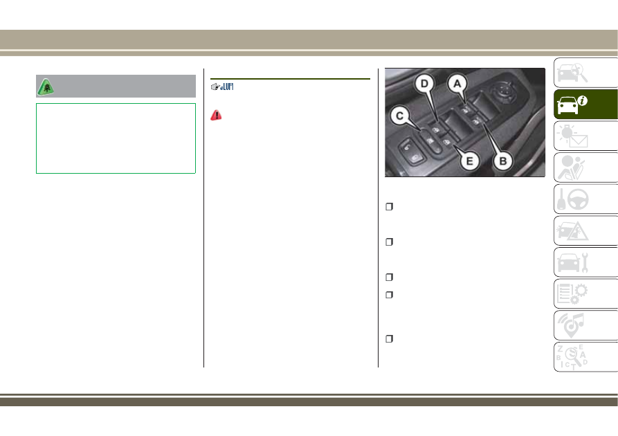
Driver side front door controls

The buttons are located on the trims of
the left side door panels (left hand drive
versions) or of the right side door panels
(right hand drive versions). All windows
can be controlled from the driver side
door panel fig. 39.

A: front left window opening/closing.

"Continuous automatic" operation during
window opening/closing stage and
anti-pinch system activated.

B: right front window opening/closing.

"Continuous automatic" operation during
window opening/closing stage and
anti-pinch system activated.

C: enabling/disabling of rear door

electric window controls;

D: left rear window opening/closing (if

present). "Automatic continuous"
operation during window opening/closing,
manual electric operation during window
closing;

E: right rear window opening/closing

(if present). "Automatic continuous"
operation during window opening/closing,

39

J0A0078C

45

manual electric operation during window
closing.

Window opening
Push the buttons to open the desired
window.
When any of the opening buttons on front
or rear doors is pressed briefly, the
window moves in stages; if the button is
held down, "continuous automatic"
operation is activated.
If the button is pressed again, the
window will stop in the desired position.

Window closing
Lift the buttons to close the desired
window.
The window closing stage occurs
following the same logic described for
the opening stage, for the front door
windows only.
The rear door windows can only be closed
"in stages".

Front window anti-pinch safety device

(where provided)
This safety system can recognise the
presence of any obstacle during the
window closing movement. If this occurs,
the system stops the window's movement
and reverts it by a few centimetres,
depending on its position.
The anti-crush safety function is

activated both during the manual and the
automatic operation of the window.

Electric window system initialisation

If power supply is interrupted, the
electric window automatic operation
must be reinitialised.
The initialisation procedure described
below must be carried out with the doors
closed and for each door:

fully close the window to be

initialised, with manual operation;

after the window has reached the

upper end of travel, hold the up button
down for at least 3 seconds.

WARNING

22) Incorrect use of the electric windows
may be dangerous. Before and during their
operation, ensure that any passengers are
not at risk from the moving glass either by
personal objects getting caught in the
mechanism or by being hit by it directly.
When leaving the vehicle (equipped with
mechanical key with remote control),
always remove the key from the ignition
device to prevent accidental operation of
the electric windows from being a hazard
for those still on board.

ELECTRIC SUN ROOF

23)

11)

The electric sun roof comprises two glass
panels (the front one is mobile and the
rear one fixed) and is fitted with an
electrically operated sun blind.
On some versions, the front panel might
be electrically operated.
The sun roof and the blind can be
operated only with the ignition device
turned to MAR.

CONTROL BUTTONS

Button A fig. 40: press the button on the
front glass panel to open it fully. Pull the
button: the front panel will close fully.
Press button A again during automatic
opening and closing to stop the blind
movement.

46

GETTING

TO

KNOW

YOUR

CAR

Button B fig. 40: Briefly press button B
will open the sunshade blind in “steps”.
Pressing the button for longer, instead,
will activate “continuous automatic”
opening. Briefly pulling the button will
give a “snap” closing of the sunshade
blind. Keeping the button pulled,

instead, will activate “continuous
automatic” closing.
Button C fig. 40: press and release the
button to move the roof to the “spoiler”
position (swivel opening). This type of
swivel opening can be activated
irrespective of the position of the
sunroof. During “spoiler” opening, any
pressure on button C stops the roof
closing. Press button C with the roof fully
closed to open the roof to the “swivel”
position. If the roof is positioned between
the fully open position and the “swivel”
position, press button C to close it
manually.

ANTI-PINCH DEVICE

The sun roof and the electric blind are
equipped with an anti-pinch safety
system capable of detecting the presence
of an obstacle whilst the roof is closing:
if this happens, the system intervenes
and the movement of the glass is
immediately reversed.

EMERGENCY OPERATION

If the control buttons fail to operate, the
sun blind and the sun roof can be moved
manually, proceeding as described
below:

Sun blind movement: remove protective

cap A fig. 41 on the internal trim;

Sun roof movement: remove protective

cap B on the internal trim;

take the supplied spanner C from the

luggage compartment;

insert key C in housing A (for blind

movement) or B (for sun roof movement)
and turn it clockwise to open the roof (or
the blind) or anticlockwise to close the
roof (or the blind).

INITIALISATION PROCEDURE

Following an automatic movement
malfunction while opening/closing or
after an emergency manoeuvre (see
description in the previous paragraph),
the automatic operation of the sun roof
must be initialised again.

40

J0A0224C

41

J0A00390C

47

Proceed as follows:

move the roof to fully closed position;

move the ignition device to STOP and

keep it there for 10 seconds;

move the ignition device to MAR;

press button A: fig. 40 in "closing"

position;

press the button for at least

10 seconds, then you should hear the
mechanical stop of the roof motor;

press the button A in the "closing"

position again within 5 seconds;

hold down button A: in this position,

the roof will perform an automatic
opening and closing cycle. Otherwise,
repeat the operations starting from the
beginning;

hold down button A until the roof is

completely closed: the initialisation
procedure has ended.

WARNING

23) When leaving the vehicle (equipped
with mechanical key with a remote
control), always remove the key from the
ignition device to avoid the risk of injury
to those still inside the vehicle due to
accidental operation of the sun roof.
Improper use of the roof can be
dangerous. Before and during operation,
always check that no-one is exposed to the
risk of being injured by the moving
sunroof or by objects getting caught or hit
by it.

IMPORTANT

11) Do not open the sun roof if a
transverse roof rack is fitted. Do not open
the sun roof if there is snow or ice on it:
you may damage it.

MySky SUN ROOF

12)

The roof has two panels, a front and a
rear one, that can be individually or
simultaneously removed, as wished.
Front and rear panels are distinguished
by a dedicated symbol on the bottom of
the panels themselves.

IMPORTANT The panels can withstand
any snow that may deposit on them. In
any case, it is advisable to remove
excessive snow.

FRONT PANEL ELECTRIC
MOVEMENT

On some versions, the front panel might
be electrically operated.
This operates only with the ignition
device at MAR. The panel can be
adjusted forward/backward and opened
in “swivel” position.
The buttons to operate the front panel
are located on the trim close to the front
ceiling light fig. 42:

Button A: open/close the front panel to

the end of its travel. Press button A to
fully open the front glass panel. Pull the
button: the front panel will close fully.

48

GETTING

TO

KNOW

YOUR

CAR

Button B: opening button for “swivel”

position of the front panel. Press and
release button B to bring the roof to the
“swivel” position. This opening mode can
only be activated with the roof fully
closed. Button B will be disabled when
the panel is open or partially open.
During “swivel” opening, any pressure on
button B stops the roof closing.

Anti-pinch device

The front panel has an anti-pinch safety
system that can detect an obstacle while
the panel is opening or closing. When

this happens, the system stops and the
movement of the panel is immediately
reversed.

PANEL REMOVAL

IMPORTANT Remove the panels only
when the vehicle is at a standstill. The
rear panel can be removed only when
the front panel is fully closed or
removed.

Proceed as follows to remove the panels:

working inside the passenger

compartment, fit the spanner A
fig. 43 inside the housing B fig. 44,
rotate it and continue rotating it next to
the

symbol, so that the door lock is

released; at the same time, fully pull the
handle C (on the same panel) to the end
of travel;

42

J0A0225C

49

remove the panel (front or rear) or

both panels, then take out the baffle
(located in the panel housing bag) and
engage it in the dedicated housings in

the vehicle (see fig. 45 and fig. 46 );

place the panel (or both panels) inside

the dedicated suitcase (see the following
pages) and arrange it in the luggage
compartment.

PANEL STORAGE SUITCASE

After removing the roof panels, they must
be positioned inside the dedicated
suitcase inside the luggage
compartment. It is recommended to
perform this procedure from outside the
vehicle.
Proceed as follows:

open the bag, remove the baffle A

fig. 47 and lift the devices B;

43

J0A0272C

44

J0A0271C

45

J0A0552C

46

J0A0551C

50

GETTING

TO

KNOW

YOUR

CAR

position the panels inside, making

sure that the two handles are reciprocally
opposed (see fig. 48 ), then reposition
the baffle properly in its housing;

close the bag again, position it

correctly inside the luggage compartment
and then secure the bag firmly to the
retaining hooks on the luggage
compartment crossmember (see fig. 49 ).

IMPORTANT Do not lay evenly
distributed loads on the bag if they
exceed 10 kg in weight.

EMERGENCY OPERATION

If the control buttons fail to operate, the
sun roof can be moved manually,
proceeding as described below:

remove protective cap A fig. 50 on

the internal trim;

introduce the supplied key B into

housing A and turn it clockwise to open
the roof or anticlockwise to close it.

INITIALISATION PROCEDURE

Following an automatic movement
malfunction while opening/closing or
after an emergency manoeuvre (see
description in the previous paragraph),
the automatic operation of the sunroof
must be initialised again.

47

J0A0630C

48

J0A0490C

49

J0A0417C

50

J0A0080C

51

Proceed as follows:

move the roof to fully closed position;
move the ignition device to STOP and

keep it there for 10 seconds;

bring the ignition device to MAR;
press button A fig. 42 in the “close”

position;

press the button for at least

10 seconds, then you should hear the
mechanical stop of the roof motor;

within 5 seconds, press the button A

again in the "close" position;

hold down button A in this position:

the roof will perform an automatic
opening and closing cycle. Otherwise,
repeat the operations starting from the
beginning;

hold down button A until the roof is

completely closed: the initialisation
procedure has ended.

IMPORTANT

12) Do not open the sun roof if a
transverse roof rack is fitted. Do not open
the sun roof if there is snow or ice on it:
you may damage it.

BONNET

OPENING

Proceed as follows:

pull lever A fig. 51 in the direction

indicated by the arrow;

operate lever B fig. 52, in the

direction indicated by the arrow, and
raise the bonnet;

release bonnet stay C fig. 53 from its

locking device D, then insert its end in
housing E on the bonnet.

51

J0A0364C

52

J0A0069C

52

GETTING

TO

KNOW

YOUR

CAR

24) 25)

CLOSING

Proceed as follows:

hold the bonnet up with one hand and

with the other remove the stay from the
housing E and fit it back in locking
device D;

lower the bonnet to approximately

40 centimetres from the engine
compartment and let it drop. Make sure
that the bonnet is completely closed and
not only fastened by the locking device
by trying to open it. If it is not perfectly
closed, do not try to press the bonnet lid
down but open it and repeat the
procedure.

26) 27)

IMPORTANT Always check that the
bonnet is closed correctly to prevent it
from opening while the vehicle is
travelling. Since the bonnet is
equipped with a double locking
system, one for each side, you must
check that is closed on both its side
ends.

WARNING

24) The bonnet may drop suddenly if the
supporting rod is not positioned correctly.

25) Use both hands to lift the bonnet.
Before lifting, check that the windscreen
wiper arms are not raised from the
windscreen or in operation, that the
vehicle is stationary and that the electric
parking brake is engaged.
26) For safety reasons, the bonnet must
always be properly closed while the car is
travelling. Therefore, make sure that the
bonnet is properly closed and that the lock
is engaged. If you discover that the bonnet
is not perfectly closed during travel, stop
immediately and close the bonnet in the
correct manner.
27) Perform these operations only when
the car is stationary.

53

J0A0070C

53

LUGGAGE COMPARTMENT

The luggage compartment unlocking is
electrically operated and is deactivated
when the vehicle is in motion.

OPENING FROM THE OUTSIDE

28)

When unlocked, the boot can be opened
from outside the car using the electric
opening handle A fig. 54 located under
the handle until the unlocking click is
heard or by quickly pressing button

on the remote control twice.

Emergency opening from the inside

Proceed as follows:

remove parcel shelf (where provided),

remove the rear head restraints and fully
fold the seats;

use the screwdriver to remove the

yellow tab A fig. 55;

insert the screwdriver in housing B

fig. 56, in order to activate the luggage
compartment release tab.

CLOSING

To close the luggage compartment grab
the handle located inside the tailgate.

IMPORTANT Before closing the
luggage compartment make sure that
you have the keys since the luggage
compartment is automatically locked.

54

J0A0895C

55

J0A0085C

56

J0A0214C

54

GETTING

TO

KNOW

YOUR

CAR

LUGGAGE COMPARTMENT
INITIALISATION

IMPORTANT If the battery is
disconnected or the protection fuse
blows, the luggage compartment
opening/closing mechanism must be
reinitialised as follows:

close all the doors and the luggage

compartment;

press the

button on the remote

control;

press the

button on the remote

control.

LOAD COMPARTMENT FEATURES

Reconfigurable load platform

The platform has two different positions:
the "level with ground" (position "0") or
the "all up" (position "1"). The load
platform can also be poeitioned obliquely
(inclined towards the rear seats) to ease
access to the area beneath the boot.
The load platform can be tipped, and it
comes with a handy washable plastic
covering for carrying wet or muddy items.

13)

Access/moving the reconfigurable load
platform

To access the double load platform, grab
handle A and lift it up to level B
fig. 57 holding it with one hand.

To bring the load platform from the lower
to upper position, proceed as follows:

grab handle A and lift it up to level B,

holding it with one hand;

correctly position level B onto the

slides D fig. 58 on the sides and on the
rear position E.

Power Socket

IMPORTANT Do not connect devices
with power higher than 180 W to the
socket. Do not damage the socket by
using unsuitable adaptors.

WARNING

28) Be careful not to hit objects on the
storage shelf when you open the tailgate.

57

J0A0284C

58

J0A0286C

55

IMPORTANT

13) The dimensions of the platform permit
a maximum capacity of distributed weight
of 110 kg on both positions ("0" and "1"):
do not load objects with a higher weight.

VERSION WITH LPG
SYSTEM

(where provided)

29) 30)

14) 15) 16)

INTRODUCTION

The LPG version features two fuel supply
systems: one for petrol and one for LPG.

PASSIVE SAFETY / ACTIVE
SAFETY

Although the LPG system has numerous
safety features, it is advisable to proceed
as follows every time the car is not in use
for a long period or moved in an
emergency as a result of a breakdown or
accident:

unscrew the fixing devices A fig. 59,

then remove the cover B;

close the LPG cock rotating the ring C

refit the cover and retighten the

fastening devices.

59

J0A0932C

56

GETTING

TO

KNOW

YOUR

CAR

clockwise:

LPG TANK

17)

The car has a (pressurised) tank A
fig. 61 for storing LPG in a liquid state.
It is toroidal and is located in the spare
wheel compartment with suitable
protection.

LPG tank certification

The LPG tank is certified in accordance
with the regulations in force.
In Italy, the tank has a life of 10 years
starting from the car registration date. If the
car has been registered in a country other
than Italy, the duration and the
testing/inspection procedures of the LPG
tank can vary depending on the national
provisions in force in that country. In all
case, when the time limit for your country
has expired, go to a Jeep Dealer to have the
tank replaced.

LPG/PETROL SWITCH

31)

18) 19) 20)

This engine normally runs on LPG except
during starting when it runs on petrol.
Switching to LPG is automatic.
To change fuel type, press the button
fig. 62 on the tunnel with the car
stationary and engine running or while
driving.
If you expressly want to run on petrol,
press the located on the central tunnel.
The switching on of the LED located
above the button and of the green

symbol on the display indicates that

the switching request has taken place
correctly.

60

J0A0933C

61

J0A0935C

57

The four bars on the digital indicator
near the letters LPG on the instrument
panel display indicate the level of LPG in
the tank. Switching is confirmed by the
switching on/off of the

symbol on the

display.

REFUELLING

LPG

21) 22) 23)

Maximum refuelling capacity (including
reserve): 38 litres. The figure already
takes into account the 80% tank filling
limit and the residual fluid required for
priming and the maximum permitted
capacity. In addition, after different
refuelling processes, this figure may vary

due to differences between the network
pump supply pressures, pumps having
different supply/locking features, tank not
completely run out of fuel.
IMPORTANT In order to avoid
inconsistent information by the LPG
gauge on the instrument panel, it is
recommended to refill with at least
10 litres each time.

WARNING

29) Note that in some countries (including
Italy) there are legal restrictions in force
for parking/garaging motor cars fuelled by
gas that is denser than air; LPG comes
under this category.
30) If gas is smelt, switch from LPG
operation to petrol operation and
immediately go to a Jeep Dealership to
have the car checked and possible system
faults excluded.
31) Do not switch between the two
operating modes whilst starting the
engine.
32) Modifications or repairs to the supply
system that are not carried out correctly or
do not take the system technical
specifications into account can cause
malfunctions leading to the risk of fire.

IMPORTANT

14) The system operates at temperatures
ranging between -20°C and 100°C.
15) The car is equipped with a gaseous
LPG injection system designed specifically
for it: it is therefore absolutely forbidden
to alter the configuration of the system or
its components. The use of other
components or materials could cause
malfunctions and lead to a reduction in
safety; therefore, in the case of problems,
contact a Jeep Dealership. When towing or
lifting the car, follow the instructions in
the main handbook under the paragraph
on "Towing the car" to prevent damage to
the gas system parts.
16) When painting in an oven, the LPG
tank must be removed from the car and
later refitted by a Jeep Dealership.
17) Periodically (at least once every six
months) it is advisable to let the LPG in
the tank run out and, at the first
refuelling, to check that it does not exceed
the maximum capacity of 38 litres (reserve
included) (with a tolerance of 2 litres
excess). If the level is above 38 litres
(reserve included) contact a Jeep
Dealership immediately.

62

J0A0930C

58

GETTING

TO

KNOW

YOUR

CAR

18) Regardless of the last fuel system
used, at the following engine starting, after
the initial petrol stage, the system will
automatically switch to LPG.
19) When switching is requested, metallic
noise from the valves which pressurise the
circuit can be heard. For the switching
logic described above, a delay between the
valve ticking and the switching off of the
instrument panel indication is completely
normal.

20) In particular usage conditions, such as
starting and operation at low ambient
temperature or LPG supply with low
propane content, the system may switch
temporarily to petrol operation, without a
visual indication of switching on the
instrument panel. In the event of low LPG
levels in the tank or requests for high
performance (e.g. overtaking, vehicle fully
laden, steep hills) the system may
automatically switch to running on petrol
to guarantee the required engine power;
the green icon

on the instrument panel

display turns on to indicate this. When the
above conditions are no longer present,
the system automatically restores LPG
operating mode; the green symbol

switches off. To achieve the automatic

switching described above, make sure that
there is always enough fuel in the petrol
tank.
21) Only use LPG for motor vehicles.
22) It is strictly forbidden to use any
additive in the LPG.

23) Periodically (at least once every six
months) it is advisable to let the LPG in
the tank run out and, at the first
refuelling, to check that it does not exceed
the maximum capacity of 38 litres (reserve
included) (with a tolerance of 2 litres
excess). If the level is above 38 litres
(reserve included) contact a Jeep
Dealership immediately.

59


Content   ..  1  2  3  4   ..