Jeep Grand Cherokee (2019 year). Instruction - part 23


  Index      Jeep     Jeep Grand Cherokee - instruction 2019 year in english


Search            


Content   ..  21  22  23  24   ..


Jeep Grand Cherokee (2019 year). Instruction - part 23


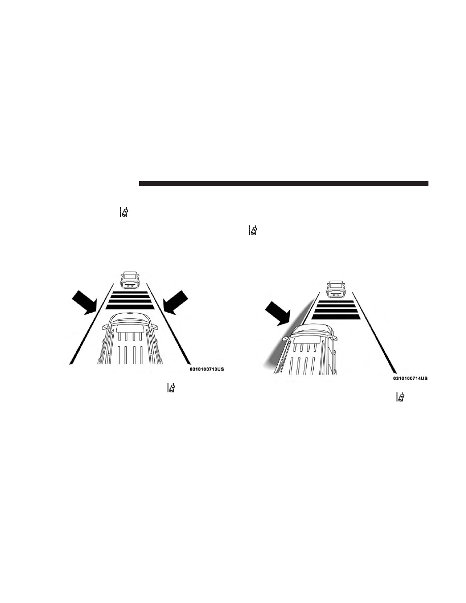
• When the LaneSense system senses a lane drift situation,

the left thick lane line and left thin line turn solid yellow.
The LaneSense telltale

changes from solid green to

solid yellow. At this time torque is applied to the
steering wheel in the opposite direction of the lane
boundary.

• For example: If approaching the left side of the lane the

steering wheel will turn to the right.

• When the LaneSense system senses the lane has been

approached and is in a lane departure situation, the left
thick lane line flashes yellow (on/off) and the left thin
line remains solid yellow. The LaneSense telltale

changes from solid yellow to flashing yellow. At

this time torque is applied to the steering wheel in the
opposite direction of the lane boundary.

• For example: If approaching the left side of the lane the

steering wheel will turn to the right.

NOTE:

The LaneSense system operates with the similar

behavior for a right lane departure.

Lane Sensed (Solid Yellow Thick Line, Solid Yellow Thin

Line/Solid Yellow Telltale

)

Lane Approached (Flashing Yellow Thick Line, Solid

Yellow Thin Line/Flashing Yellow Telltale

)

356

STARTING AND OPERATING

Changing LaneSense Status

The LaneSense system has settings to adjust the intensity of
the torque warning and the warning zone sensitivity
(early/late) that you can configure through the Uconnect
system screen. Refer to “Uconnect Settings” in “Multime-
dia” for further information.

NOTE:
• When enabled the system operates above 37 mph

(60 km/h) and below 112 mph (180 km/h).

• Use of the turn signal suppresses the warnings.
• The system will not apply torque to the steering wheel

whenever a safety system engages (anti-lock brakes,
traction control system, electronic stability control, for-
ward collision warning, etc.).

PARKVIEW REAR BACK UP CAMERA

The ParkView Rear Back Up Camera allows you to see an
on-screen image of the rear surroundings of your vehicle
whenever the gear selector is put into REVERSE. The
image will be displayed on the Navigation/Multimedia
radio display screen along with a caution note to “check
entire surroundings” across the top of the screen. After five

seconds this note will disappear. The ParkView camera is
located on the rear of the vehicle above the rear license
plate.

When the vehicle is shifted out of REVERSE (with camera
delay turned off), the rear camera mode is exited and the
navigation or audio screen appears again.

Manual Activation Of The Rear View Camera

1. Press the “Controls” button located on the bottom of the

Uconnect display.

2. Press the “Backup Camera” button to turn the Rear

View Camera system on.

NOTE:

The ParkView Rear Back Up Camera has program-

mable modes of operation that may be selected through the
Uconnect System.

Refer to “Uconnect Settings” in “Multimedia” for further
information.

When the vehicle is shifted out of REVERSE (with camera
delay turned off), the rear camera mode is exited and the
previous screen appears again. When the vehicle is shifted
out of REVERSE (with camera delay turned on), the camera
image will continue to be displayed for up to ten seconds
after shifting out of REVERSE unless the vehicle speed

6

STARTING AND OPERATING

357

exceeds 8 mph (13 km/h), the vehicle is shifted into PARK,
the vehicle’s ignition is cycled to the OFF position, or the
user presses image defeat [X] to exit out of the camera
video display.

When enabled, active guide lines are overlaid on the image
to illustrate the width of the vehicle and its projected
backup path based on the steering wheel position. A

dashed center line overlay indicates the center of the
vehicle to assist with parking or aligning to a hitch/
receiver. Different colored zones indicate the distance to the
rear of the vehicle. The following table shows the approxi-
mate distances for each zone:

Zone

Distance To The Rear Of The Vehicle

Red

0 - 1 ft (0 - 30 cm)

Yellow

1 ft - 6.5 ft (30 cm - 2 m)

Green

6.5 ft or greater (2 m or greater)

WARNING!

Drivers must be careful when backing up even when
using the ParkView Rear Back Up Camera. Always
check carefully behind your vehicle, and be sure to
check for pedestrians, animals, other vehicles, obstruc-
tions, or blind spots before backing up. You are re-
sponsible for the safety of your surroundings and must
continue to pay attention while backing up. Failure to
do so can result in serious injury or death.

CAUTION!

• To avoid vehicle damage, ParkView should only be

used as a parking aid. The ParkView camera is
unable to view every obstacle or object in your drive
path.

• To avoid vehicle damage, the vehicle must be driven

slowly when using ParkView to be able to stop in
time when an obstacle is seen. It is recommended
that the driver look frequently over his/her shoulder
when using ParkView.

358

STARTING AND OPERATING

NOTE:

If snow, ice, mud, or any foreign substance builds

up on the camera lens, clean the lens, rinse with water, and
dry with a soft cloth. Do not cover the lens.

Rear Camera — Viewing At Speed

When the vehicle is in park, neutral or drive, the Rear View
Camera can be activated with the “Rear View Camera”
button

in the Controls menu. This feature allows the

customer to monitor the area directly behind the vehicle
(or trailer, if equipped) for up to ten seconds while at
speed. If the vehicle speed remains below 8 mph
(13 km/h), the Rear View Camera image will be dis-
played continuously until deactivated via the “X” but-
ton on the touchscreen.

REFUELING THE VEHICLE — GASOLINE ENGINE

1. Push the fuel filler door release switch (located under

the headlamp switch).

2. Open the fuel filler door.

Fuel Filler Door Release Switch

6

STARTING AND OPERATING

359

NOTE:

In certain cold conditions, ice may prevent the fuel

door from opening. If this occurs, lightly push on the fuel
door to break the ice buildup and re-release the fuel door
using the inside release button. Do not pry on the door.

3. There is no fuel filler cap. Two flapper doors inside the

pipe seals the system.

4. Insert the fuel nozzle fully into the filler pipe, the nozzle

opens and holds the flapper doors while refueling.

5. Fill the vehicle with fuel, when the fuel nozzle “clicks”

or shuts off the fuel tank is full.

6. Wait five seconds before removing the fuel nozzle to

allow fuel to drain from nozzle.

7. Remove the fuel nozzle and close the fuel door.

Emergency Gas Can Refueling

Most gas cans will not open the flapper doors.

A funnel is provided to open the flapper doors to allow
emergency refueling with a gas can.

1. Retrieve funnel from the spare tire storage area.

2. Insert funnel into same filler pipe opening as the fuel

nozzle.

3. Ensure funnel is inserted fully to hold flapper doors

open.

4. Pour fuel into funnel opening.

5. Remove funnel from filler pipe, clean off prior to putting

back in the spare tire storage area.

Fuel Filler Door Latch

360

STARTING AND OPERATING

WARNING!

• Never have any smoking materials lit in or near the

vehicle when the fuel door is open or the tank is
being filled.

• Never add fuel when the engine is running. This is

in violation of most state and federal fire regulations
and may cause the “Malfunction Indicator Light” to
turn on.

• A fire may result if fuel is pumped into a portable

container that is inside of a vehicle. You could be
burned. Always place fuel containers on the ground
while filling.

CAUTION!

To avoid fuel spillage and overfilling, do not “top off”
the fuel tank after filling.

Emergency Fuel Filler Door Release

If you are unable to open the fuel filler door, use the fuel
filler door emergency release.

1. Open the liftgate.

2. Push the inboard edge of the left storage bin to the

center, this will pop up the outboard edge.

3. Grab popped up outboard edge with other hand to

disengage snaps.

4. Remove the storage bin.

5. Pull the release cable to open the fuel door, push the

release cable back to the home position to re-seat the fuel
door latch to the closed position.

Release Cable

6

STARTING AND OPERATING

361

NOTE:

If the fuel door does not latch after the manual

release cable has been activated, the actuator latch should
be manually returned to the closed position.

VEHICLE LOADING

Certification Label

As required by National Highway Traffic Safety Adminis-
tration regulations, your vehicle has a certification label
affixed to the driver’s side door or pillar.

This label contains the month and year of manufacture,
Gross Vehicle Weight Rating (GVWR), Gross Axle Weight
Rating (GAWR) front and rear, and Vehicle Identification
Number (VIN). A Month-Day-Hour (MDH) number is
included on this label and indicates the Month, Day and
Hour of manufacture. The bar code that appears on the
bottom of the label is your VIN.

Gross Vehicle Weight Rating (GVWR)

The GVWR is the total permissible weight of your vehicle
including driver, passengers, vehicle, options and cargo.
The label also specifies maximum capacities of front and
rear axle systems (GAWR). Total load must be limited so
GVWR and front and rear GAWR are not exceeded.

Payload

The payload of a vehicle is defined as the allowable load
weight a truck can carry, including the weight of the driver,
all passengers, options and cargo.

Gross Axle Weight Rating (GAWR)

The GAWR is the maximum permissible load on the front
and rear axles. The load must be distributed in the cargo
area so that the GAWR of each axle is not exceeded.

Each axle GAWR is determined by the components in the
system with the lowest load carrying capacity (axle,
springs, tires or wheels). Heavier axles or suspension
components sometimes specified by purchasers for in-
creased durability does not necessarily increase the vehi-
cle’s GVWR.

Tire Size

The tire size on the Vehicle Certification Label represents
the actual tire size on your vehicle. Replacement tires must
be equal to the load capacity of this tire size.

362

STARTING AND OPERATING

Rim Size

This is the rim size that is appropriate for the tire size
listed.

Inflation Pressure

This is the cold tire inflation pressure for your vehicle for
all loading conditions up to full GAWR.

Curb Weight

The curb weight of a vehicle is defined as the total weight
of the vehicle with all fluids, including vehicle fuel, at full
capacity conditions, and with no occupants or cargo loaded
into the vehicle. The front and rear curb weight values are
determined by weighing your vehicle on a commercial
scale before any occupants or cargo are added.

Loading

The actual total weight and the weight of the front and rear
of your vehicle at the ground can best be determined by
weighing it when it is loaded and ready for operation.

The entire vehicle should first be weighed on a commercial
scale to insure that the GVWR has not been exceeded. The
weight on the front and rear of the vehicle should then be
determined separately to be sure that the load is properly
distributed over the front and rear axle. Weighing the
vehicle may show that the GAWR of either the front or rear
axles has been exceeded but the total load is within the
specified GVWR. If so, weight must be shifted from front to
rear or rear to front as appropriate until the specified
weight limitations are met. Store the heavier items down
low and be sure that the weight is distributed equally. Stow
all loose items securely before driving.

Improper weight distributions can have an adverse effect
on the way your vehicle steers and handles and the way
the brakes operate.

CAUTION!

Do not load your vehicle any heavier than the GVWR
or the maximum front and rear GAWR. If you do, parts
on your vehicle can break, or it can change the way
your vehicle handles. This could cause you to lose
control. Also overloading can shorten the life of your
vehicle.

6

STARTING AND OPERATING

363

TRAILER TOWING

In this section you will find safety tips and information on
limits to the type of towing you can reasonably do with
your vehicle. Before towing a trailer, carefully review this
information to tow your load as efficiently and safely as
possible.

To maintain the New Vehicle Limited Warranty coverage,
follow the requirements and recommendations in this
manual concerning vehicles used for trailer towing.

Common Towing Definitions

The following trailer towing related definitions will assist
you in understanding the following information:

Gross Vehicle Weight Rating (GVWR)

The GVWR is the total allowable weight of your vehicle.
This includes driver, passengers, cargo and tongue weight.
The total load must be limited so that you do not exceed
the GVWR. Refer to “Vehicle Loading/Vehicle Certification
Label” in “Starting And Operating” for further informa-
tion.

Gross Trailer Weight (GTW)

The GTW is the weight of the trailer plus the weight of all
cargo, consumables and equipment (permanent or tempo-
rary) loaded in or on the trailer in its

⬙loaded and ready for

operation

⬙ condition.

The recommended way to measure GTW is to put your
fully loaded trailer on a vehicle scale. The entire weight of
the trailer must be supported by the scale.

WARNING!

If the gross trailer weight is 5,000 lbs (2,267 kg) or more,
it is recommended to use a weight-distributing hitch to
ensure stable handling of your vehicle. If you use a
standard weight-carrying hitch, you could lose control
of your vehicle and cause a collision.

Gross Combination Weight Rating (GCWR)

The GCWR is the total allowable weight of your vehicle
and trailer when weighed in combination.

364

STARTING AND OPERATING

Gross Axle Weight Rating (GAWR)

The GAWR is the maximum capacity of the front and rear
axles. Distribute the load over the front and rear axles
evenly. Make sure that you do not exceed either front or
rear GAWR. Refer to “Vehicle Loading/Vehicle Certifica-
tion Label” in “Starting And Operating” for further infor-
mation.

WARNING!

It is important that you do not exceed the maximum
front or rear GAWR. A dangerous driving condition
can result if either rating is exceeded. You could lose
control of the vehicle and have a collision.

Tongue Weight (TW)

The tongue weight is the downward force exerted on the
hitch ball by the trailer. You must consider this as part of
the load on your vehicle.

Trailer Frontal Area

The frontal area is the maximum height multiplied by the
maximum width of the front of a trailer.

Trailer Sway Control

The trailer sway control can be a mechanical telescoping
link that can be installed between the hitch receiver and the
trailer tongue that typically provides adjustable friction
associated with the telescoping motion to dampen any
unwanted trailer swaying motions while traveling.

If equipped, the electronic Trailer Sway Control (TSC)
recognizes a swaying trailer and automatically applies
individual wheel brakes and/or reduces engine power to
attempt to eliminate the trailer sway.

Weight-Carrying Hitch

A weight-carrying hitch supports the trailer tongue weight,
just as if it were luggage located at a hitch ball or some
other connecting point of the vehicle. These kinds of
hitches are the most popular on the market today and they
are commonly used to tow small and medium sized
trailers.

6

STARTING AND OPERATING

365

Weight-Distributing Hitch

A weight-distributing system works by applying leverage
through spring (load) bars. They are typically used for
heavier loads to distribute trailer tongue weight to the tow
vehicle’s front axle and the trailer axle(s). When used in
accordance with the manufacturer’s directions, it provides
for a more level ride, offering more consistent steering and
brake control thereby enhancing towing safety. The addi-
tion of a friction/hydraulic sway control also dampens
sway caused by traffic and crosswinds and contributes
positively to tow vehicle and trailer stability. Trailer sway
control and a weight distributing (load equalizing) hitch
are recommended for heavier Tongue Weights (TW) and
may be required depending on vehicle and trailer
configuration/loading to comply with Gross Axle Weight
Rating (GAWR) requirements.

WARNING!

• An improperly adjusted Weight Distributing Hitch

system may reduce handling, stability, braking per-
formance, and could result in a collision.

• Weight Distributing Systems may not be compatible

with Surge Brake Couplers. Consult with your hitch
and trailer manufacturer or a reputable Recreational
Vehicle dealer for additional information.

Trailer Hitch Classification

The following chart provides the industry standard for the
maximum trailer weight a given trailer hitch class can tow
and should be used to assist you in selecting the correct
trailer hitch for your intended towing condition.

366

STARTING AND OPERATING

Trailer Hitch Classification Definitions

Class

Max. Trailer Hitch Industry Standards

Class I - Light Duty

2,000 lbs (907 kg)

Class II - Medium Duty

3,500 lbs (1,587 kg)

Class III - Heavy Duty

5,000 lbs (2,267 kg)

Class IV - Extra Heavy Duty

10,000 lbs (4,535 kg)

Refer to the “Trailer Towing Weights (Maximum Trailer Weight Ratings)” chart for the Maximum Gross Trailer Weight
(GTW) towable for your given drivetrain.
All trailer hitches should be professionally installed on your vehicle.

Trailer Towing Weights (Maximum Trailer Weight Ratings)

The following chart provides the maximum trailer weight ratings towable for your given drivetrain:

Engine

Model

Frontal Area

Max. GTW (Gross

Trailer Wt.)

Max. Trailer Tongue

Wt. (See Note)

3.6L (Std Cooling)

4x2

55 sq ft (5.11 sq m)

3,500 lbs (1,587 kg)

350 lbs (158 kg)

3.6L (Std Cooling)

4x4

55 sq ft (5.11 sq m)

3,500 lbs (1,587 kg)

350 lbs (158 kg)

3.6L (HD Cooling)

4x2

55 sq ft (5.11 sq m)

6,200 lbs (2,812 kg)

620 lbs (281 kg)

3.6L (HD Cooling)

4x4

55 sq ft (5.11 sq m)

6,200 lbs (2,812 kg)

620 lbs (281 kg)

5.7L (Std Cooling)

4x4

55 sq ft (5.11 sq m)

5,000 lbs (2,267 kg)

500 lbs (226 kg)

5.7L (HD Cooling)

4x4

55 sq ft (5.11 sq m)

7,200 lbs (3,265 kg)

720 lbs (326 kg)

Refer to local laws for maximum trailer towing speeds.

6

STARTING AND OPERATING

367

NOTE:

The trailer tongue weight must be considered as

part of the combined weight of occupants and cargo, and
should never exceed the weight referenced on the Tire and
Loading Information placard. Refer to “Tires” in “Servicing
And Maintenance” for further information. The addition of
passengers and cargo may require reducing trailer tongue
load and Gross Trailer Weight (GTW). Redistributing cargo
(to the trailer) may be necessary to avoid exceeding Rear
Gross Axle Weight Rating (GAWR) of 3,700 lbs (1,678 kg).

Trailer Hitch Receiver Cover Removal (Summit
Models) — If Equipped

Your vehicle may be equipped with a trailer hitch receiver
cover, this must be removed to access the trailer hitch
receiver (if equipped). This hitch receiver cover is located
at the bottom center of the rear fascia.

1. Turn the two locking retainers located at the bottom of

the hitch receiver cover a 1/4 turn counterclockwise.

NOTE:

Use a suitable tool such as a coin in the slot of the

locking retainer if needed for added leverage.

2. Pull the bottom of the cover outward (towards you),

pull downwards to disengage the tabs located at the top
of the hitch receiver cover.

Hitch Receiver Cover

1 — Hitch Receiver Cover
2 — Locking Retainers

368

STARTING AND OPERATING

To reinstall the hitch receiver cover after towing repeat the
procedure in reverse order.

NOTE:

Be sure to engage all tabs of the hitch receiver cover

in the bumper fascia prior to installation.

Trailer And Tongue Weight

Never exceed the maximum tongue weight stamped on
your bumper or trailer hitch.

CAUTION!

Always load a trailer with 60% of the weight in the
front of the trailer. This places 10% of the GTW on the
tow hitch of your vehicle. Loads balanced over the
wheels or heavier in the rear can cause the trailer to
sway severely side to side which will cause loss of
control of the vehicle and trailer. Failure to load trailers
heavier in front is the cause of many trailer collisions.

Hitch Receiver Cover

Weight Distribution

6

STARTING AND OPERATING

369

Consider the following items when computing the weight
on the rear axle of the vehicle:
• The tongue weight of the trailer.
• The weight of any other type of cargo or equipment put

in or on your vehicle.

• The weight of the driver and all passengers.

NOTE:

Remember that everything put into or on the

trailer adds to the load on your vehicle. Also, additional
factory-installed options or dealer-installed options must
be considered as part of the total load on your vehicle.
Refer to the “Tire And Loading Information” placard for
the maximum combined weight of occupants and cargo for
your vehicle.

Towing Requirements

To promote proper break-in of your new vehicle drivetrain
components, the following guidelines are recommended.

CAUTION!

• Do not tow a trailer at all during the first 500 miles

(805 km) the new vehicle is driven. The engine, axle
or other parts could be damaged.

(Continued)

CAUTION! (Continued)

• Then, during the first 500 miles (805 km) that a trailer

is towed, do not drive over 50 mph (80 km/h) and do
not make starts at full throttle. This helps the engine
and other parts of the vehicle wear in at the heavier
loads.

Perform the maintenance listed in the “Scheduled Servic-
ing”. Refer to “Scheduled Servicing” in “Servicing And
Maintenance” for the proper maintenance intervals. When
towing a trailer, never exceed the GAWR or GCWR ratings.

WARNING!

Improper towing can lead to a collision. Follow these
guidelines to make your trailer towing as safe as
possible:

• Make certain that the load is secured in the trailer

and will not shift during travel. When trailering
cargo that is not fully secured, dynamic load shifts
can occur that may be difficult for the driver to
control. You could lose control of your vehicle and
have a collision.

(Continued)

370

STARTING AND OPERATING

WARNING! (Continued)

• When hauling cargo or towing a trailer, do not

overload your vehicle or trailer. Overloading can
cause a loss of control, poor performance or damage
to brakes, axle, engine, transmission, steering, sus-
pension, chassis structure or tires.

• Safety chains must always be used between your

vehicle and trailer. Always connect the chains to the
hook retainers of the vehicle hitch. Cross the chains
under the trailer tongue and allow enough slack for
turning corners.

• Vehicles with trailers should not be parked on a

grade. When parking, apply the parking brake on the
tow vehicle. Put the tow vehicle transmission in
PARK. For four-wheel drive vehicles, make sure the
transfer case is not in NEUTRAL. Always, block or

chockⴖ the trailer wheels.

• GCWR must not be exceeded.

(Continued)

WARNING! (Continued)

• Total weight must be distributed between the tow

vehicle and the trailer such that the following four
ratings are not exceeded:

1. GVWR

2. GTW

3. GAWR

4. Tongue weight rating for the trailer hitch utilized.

Towing Requirements — Tires
• Do not attempt to tow a trailer while using a compact

spare tire.

• Do not drive more than 50 mph (80 km/h) when towing

while using a full size spare tire.

• Proper tire inflation pressures are essential to the safe

and satisfactory operation of your vehicle. Refer to
“Tires” in “Servicing And Maintenance” for proper tire
inflation procedures.

6

STARTING AND OPERATING

371


Content   ..  21  22  23  24   ..