Jeep Grand Cherokee WJ. Manual - part 375
(12) Connect
automatic
transmission
cable
at
throttle body (if equipped).
(13) Install oxygen sensor wiring clip nuts to fuel
rail mounting studs (certain emissions packages
only).
(14) Install air tube (or duct) at top of throttle
body.
(15) Install fuel tank cap.
(16) Connect negative battery cable to battery.
(17) Start engine and check for fuel leaks.
FUEL INJECTOR RAIL—4.7L V–8 ENGINE
WARNING: THE FUEL SYSTEM IS UNDER CON-
STANT
PRESSURE
EVEN
WITH
ENGINE
OFF.
BEFORE SERVICING FUEL RAIL, FUEL SYSTEM
PRESSURE MUST BE RELEASED.
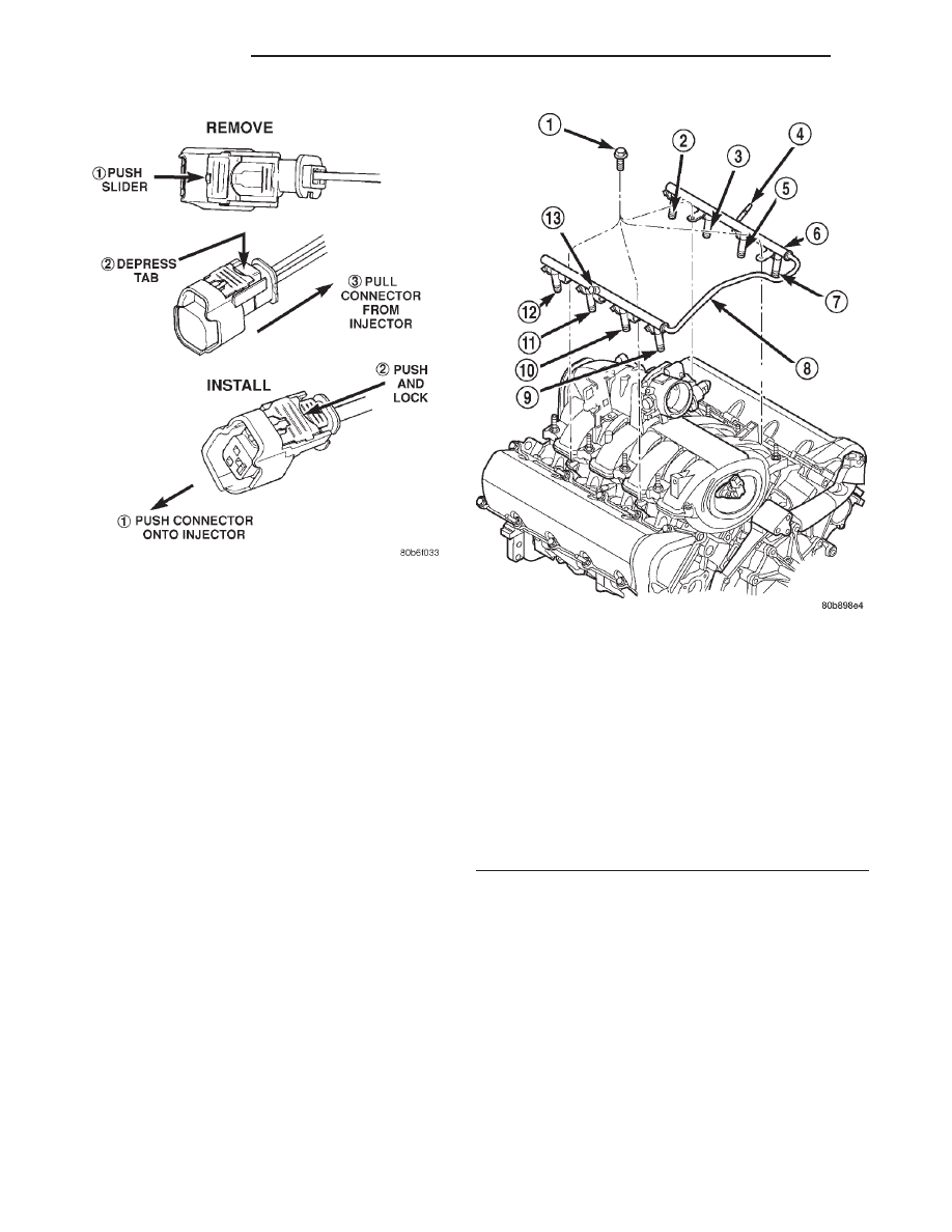
CAUTION: The left and right fuel rails are replaced
as an assembly. Do not attempt to separate rail
halves at connector tube (Fig. 35). Due to design of
tube, it does not use any clamps. Never attempt to
install a clamping device of any kind to tube. When
removing fuel rail assembly for any reason, be care-
ful not to bend or kink tube.
REMOVAL
(1) Remove fuel tank filler tube cap.
(2) Perform Fuel System Pressure Release Proce-
dure.
(3) Remove negative battery cable at battery.
(4) Remove air duct at throttle body air box.
(5) Remove air box at throttle body.
(6) Remove wiring at rear of generator.
(7) Disconnect fuel line latch clip and fuel line at
fuel rail. A special tool will be necessary for fuel line
disconnection. Refer to Quick-Connect Fittings.
(8) Remove vacuum lines at throttle body.
(9) Disconnect electrical connectors at all 8 fuel
injectors. To remove connector refer to (Fig. 36). Push
red colored slider away from injector (1). While push-
ing slider, depress tab (2) and remove connector (3)
Fig. 34 Remove/Install Injector Connector—4.0L
Engine
Fig. 35 Fuel Rail Mounting—4.7L V-8 Engine
1 – MOUNTING BOLTS (4)
2 – INJ.#7
3 – INJ.#5
4 – QUICK-CONNECT FITTING
5 – INJ.#3
6 – FUEL INJECTOR RAIL
7 – INJ.#1
8 – CONNECTOR TUBE
9 – INJ.#2
10 – INJ.#4
11 – INJ.#6
12 – INJ.#8
13 – PRESSURE TEST PORT CAP
14 - 20
FUEL SYSTEM
WJ
REMOVAL AND INSTALLATION (Continued)