Jaguar XJ (X350). Manual - part 256
-> No
REPAIR the short circuit. For additional information, refer to the wiring diagrams. Clear the DTC, test
the system for normal operation by driving the vehicle at more than 20 kph (12.5 mph) for more than
3 minutes.
G531322t103 : CHECK THE WSS SIGNAL CIRCUIT FOR SHORT CIRCUIT TO
GROUND
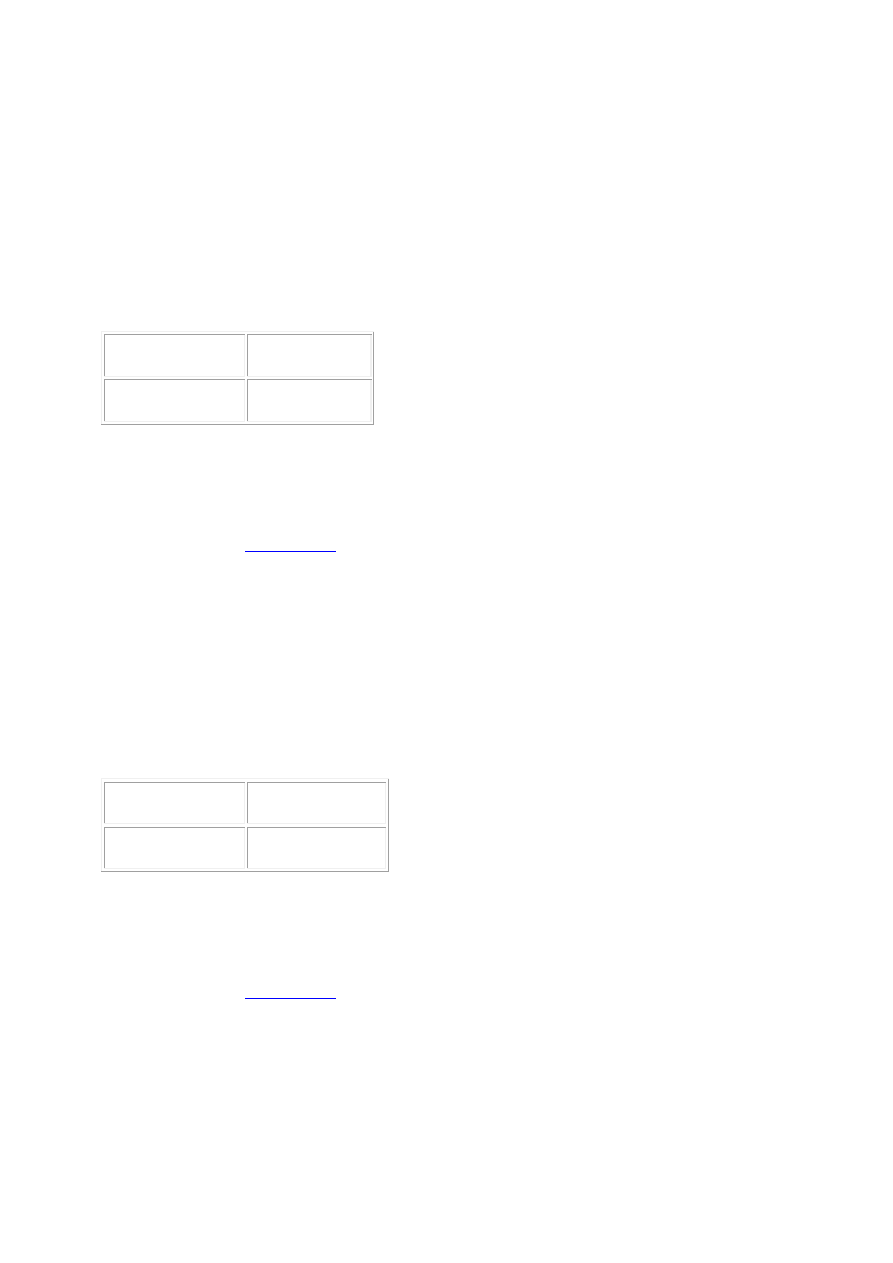
1. Measure the resistance between:
CV008, harness side
Battery
Pin 02
Negative terminal
•
Is the resistance greater than 100 Kohms?
-> Yes
GO to Pinpoint Test
G531322t104
.
-> No
REPAIR the short circuit. For additional information, refer to the wiring diagrams. Clear the DTC, test
the system for normal operation by driving the vehicle at more than 20 kph (12.5 mph) for more than
3 minutes.
G531322t104 : CHECK THE WSS SIGNAL CIRCUIT FOR HIGH RESISTANCE
1. Measure the resistance between:
CV008, harness side EC030, harness side
Pin 02
Pin 43
•
Is the resistance less than 10 ohms?
-> Yes
GO to Pinpoint Test
G531322t105
.
-> No
REPAIR the high resistance circuit. For additional information, refer to the wiring diagrams. Clear the
DTC, test the system for normal operation by driving the vehicle at more than 20 kph (12.5 mph) for
more than 3 minutes.