JAC S2. Elctrical Wiring diagrams - part 3
Air-conditioning Device
Air-conditioning Device
24
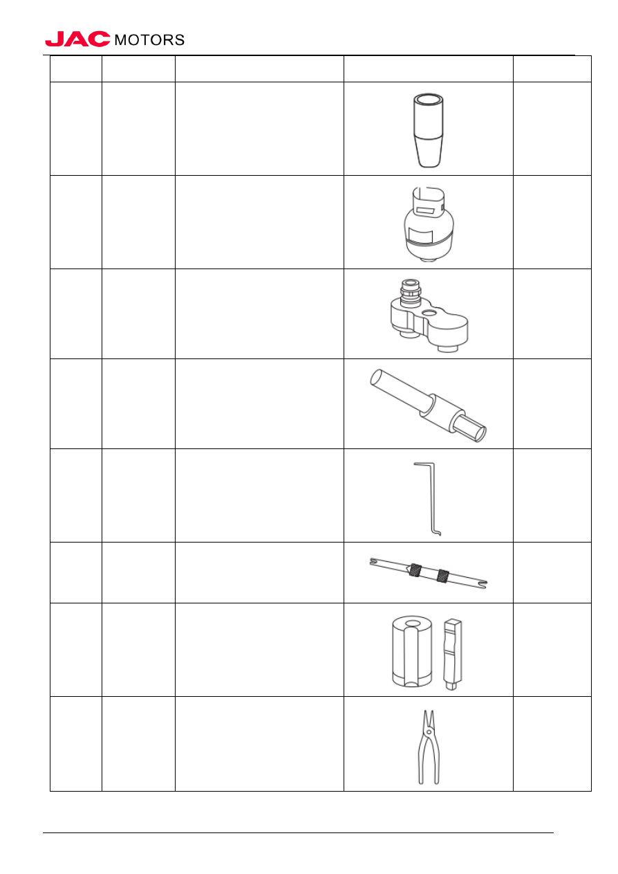
No.
Tool No.
Tool name
Outside drawing
Use
10
Seal protector device
11
50 pounds recycling tanks
12
Pressure test adapter
Connecting A/C
pressure tester and
A/C pipes
13
A/C system lip seal removal tool
Removal A/C
system lip seal
14
O-type seal removal tool
Remove O-type
seal ring
15
Valve core removal and installation tool
Remove and
install valve core
16
O-type seal ring installation tool
Install O-type seal
ring
17
Spring clip pliers
Remove and
install spring clip