JAC Trucks. Manual - part 65


  Index      JAC     JAC Trucks - service repair manual


Search            


Content   ..  63  64  65  66   ..


JAC Trucks. Manual - part 65


2. Operation Instructions

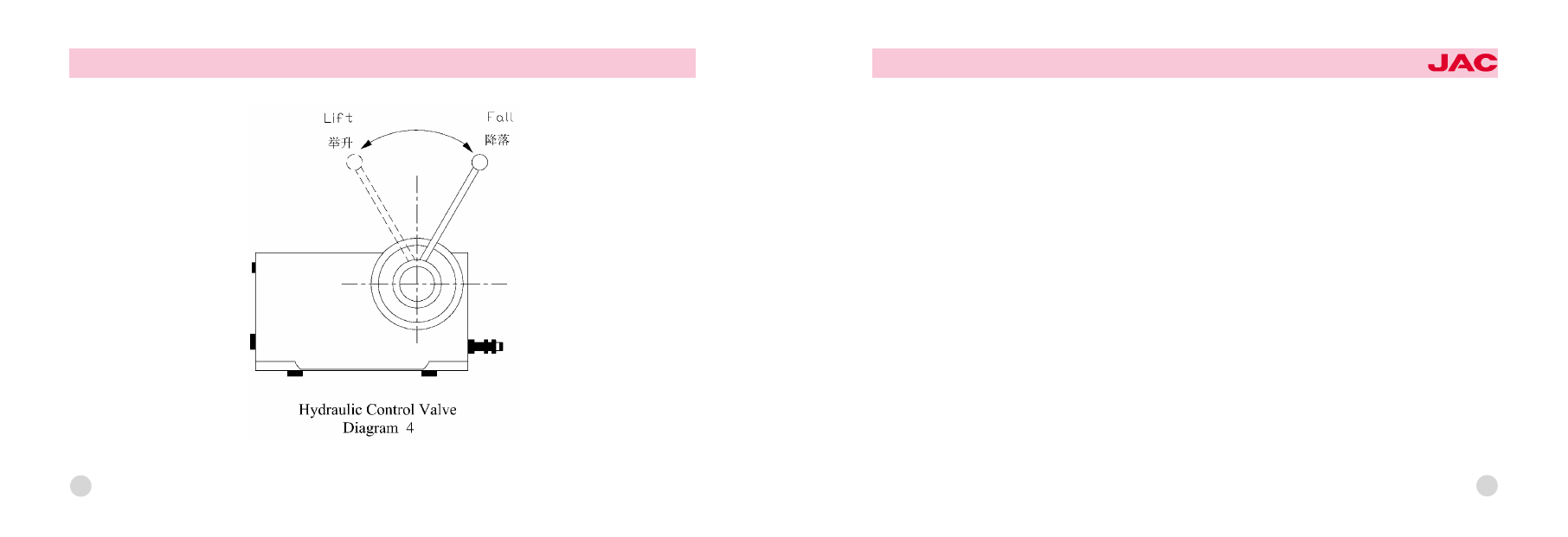
The position of the handle(from left to right)院Lift寅Fall

192

OWNER爷S MANUAL

JAC HEAVY DUTY TRUCK

Switching on the gear pump

Press the clutch pedal and turn the switch to the "on" position. Then release the clutch pedal smoothly and the gear
pump will start working.

Carriage lift

After the gear pump is started, push the control handle to "lift" and the carriage begins rising at an uniform speed. In鄄
crease the throttle and the lifting will be faster. The increase of the throttle is not permitted when the carriage is lifted to
the maximum lifting angle.

Carriage fall

Press the clutch pedal; turn off the switch; push the control handle to the "fall" position, then the carriage will start to fall.
The speed of falling can be regulated by the opening degree of the control valve.

Pause control

If you want to stop the carriage during the process of lifting, you only need to press the clutch pedal. Meanwhile, the
control valve is still on the "lift" position. But if the pause will last for a long time, you need to turn off the switch. If you
want to stop the carriage during the process of carriage fall, push the control handle from "fall" to "lift".
Note: If you want to resume the lifting after pausing, release the clutch pedal and turn off the switch.

If you want to resume the falling after pausing, push the control handle to "fall".

193

Special notes:
Before starting driving, make sure that the control handle is on the "fall" position so as to avoid the accidental carriage
lifting when the car is moving. The power take-off also needs to be switched off. Otherwise, the gear pump will continue
working, which will result in the excessive wearing and early damage of the pump.

194

OWNER爷S MANUAL

JAC HEAVY DUTY TRUCK

Working Principle and Operation Instructions of Electricity-controlled Dumping Mechanism
1. Working principle of the hydraulic system
音 The working principle of power take-off control system (see Diagram 5)

195

Diagram 5 illustrates the working principle of power take-off control system. When the switch is turned on, the com鄄
pressed air in the reservoir will flow to the power take-off cylinder through the electromagnetic valve, which will push the
gear of the power take-off to mesh with the gear of the transmission. When the power is turned off, the air in the cylin鄄
der袁under the influence of the return spring of the power take -off cylinder, will be discharged into the environment
through the vent of electromagnetic valve. The gear of the power take-off will be separated from that of the transmis鄄
sion, cutting off the power of the pump.
音 The hydraulic principle diagram of dumping system

1. hydraulic oil tank
2. gear pump
3. electromagnetic gas valve
4. air tank
5. 3-gang switch
6. air slide valve
7. hydraulic oil tub
8. the fuse

196

OWNER爷S MANUAL

JAC HEAVY DUTY TRUCK

Diagram 6 shows the hydraulic principle of the dumping system. From it we can see that the carriages in the system can
pause or fall down, free of the influences of the oil pump's working conditions. Namely, as the carriages are being
paused or falling, the oil pump can still be at work. The simplification of the operation in the pausing condition is achiev鄄
able. The air slide valve, numbered 6, which is factually a 5/4 way air control valve, helps lift, pause or drop the car鄄
riages by means of the switch (numbered 5). When the air control valve is on the left, the hydraulic oil flows through the
oil tank (1), the gear pump (2), and "P"& "A": the entrances to the air control valve fall down towards the bottom of the oil
tub, the carriages are lifted. The oil on the upper part of the tub, however, retreats to the tank by way of "B" &"O". In the
case where the air control valve is in the middle (as is signified in the diagram), the line along which the hydraulic oil fi鄄
nally returns to the tank consists of the tank, the bump gear and entrances "P"& "O"; now the carriages are paused. On
the right as the air control valve is (the carriages having been raised), part of the oil, due to the gravity of the carriages,
comes back through entrances "A"& "O" to the tank; still a certain amount of the oil goes back, passing the tank, the
bump gear and entrances P&O. Meanwhile, the downward movement of the tank's pistol renders the upper part of the
tank vacuum. Some oil, under this situation, enters the upper part of the tank through entrance B.

197

2. The operational methods
音 The PTO (Power Take Off) System
Get the engine started and make sure if it is at usual work; remember not to invigorate the gearlever. The moment the air
pressure gauge tells that the air pressure of the brake system exceeds 0.4Mpa, separate the clutch, and then, a few
seconds after the power is cut off, give a press to the button, which serves as the self-lock switch of the PTO, to turn it
on. Afterwards, slowly put through the clutch. With all of the above-mentioned procedures done, the oil pump, driven by
the PTO output shaft, is set in motion. To remove it out of work, just separate the clutch and press the button to turn off
the PTO.
音 The Lifting of the Carriages
With the oil pump at work, press the self-lock switch button for lifting and transfer the handle from "O" to "lifting", the
carriages are so raised. When they reach the most possible height, the lifting itself is no longer under way, because of
the automatic oil spill of the system. The speed of the lifting, though, is in direct proportion with that of the engine's ro鄄
tating. What should be heeded is that it is inadvisable for the carriages to be lifted too fast. Mostly, for the lifting, the en鄄
gine needs to be set under the condition of medium accelerograph, and the engine's rotating speed should be kept be鄄
low the maximum, in case the oil pump should rotate over fast, thus bringing about self-damage.
音 Bringing -down and Relocating the Carriages
As soon as the carriages are unloaded, the quicker they are brought down the better they are relocated. Press the self-
lock switch button for lifting, turn the handles from "lifting", past "O", to "bringing down", then the carriages go into gradu鄄
al falling until the final relocation comes. Now, again press the button and maintain the handles of lifting and TPO at "O";

198

OWNER爷S MANUAL

JAC HEAVY DUTY TRUCK

the vehicle gets started without delay; and the accidental lifting of carriages is simply out of question.
音 The Pausing of the Carriages
Suppose you want them to stop at a certain angle (0耀48毅) when they are being lifted or bought down, what you need to
do is merely to turn the lifting switch to "O". A momentary pause does not claim the cut-off of the PTO power, which di鄄
minishes the degree of the operational complication. Long-time pausing, however, asks for the cut-off of the power;
such being the case, the pump quits working. Therefore, improper operating which harbors accidents is hampered and
the amount of unnecessary oil-consuming finds itself reduced.
Notice: You ought to bear in mind that the controlling switch of TPO complies with electricity -liquid circuit and that of the
lifting electricity-gas-liquid circuit. So, when it comes to operating, the voltage of the battery must stay at no less than
24V and the air pressure of the gas container at no less than 0.4Mpa. Otherwise, neither the solenoid valve nor the air
slide valve would work as usual. Worse still, the valve core being closed is not tight enough, it occurs that the carriages
refuse to be lifted and paused in a steady way.

199


Content   ..  63  64  65  66   ..