Iveco EuroCargo (12 to 26 t). Manual - part 15
70171
70172
85484
Figure 50
Figure 51
Figure 52
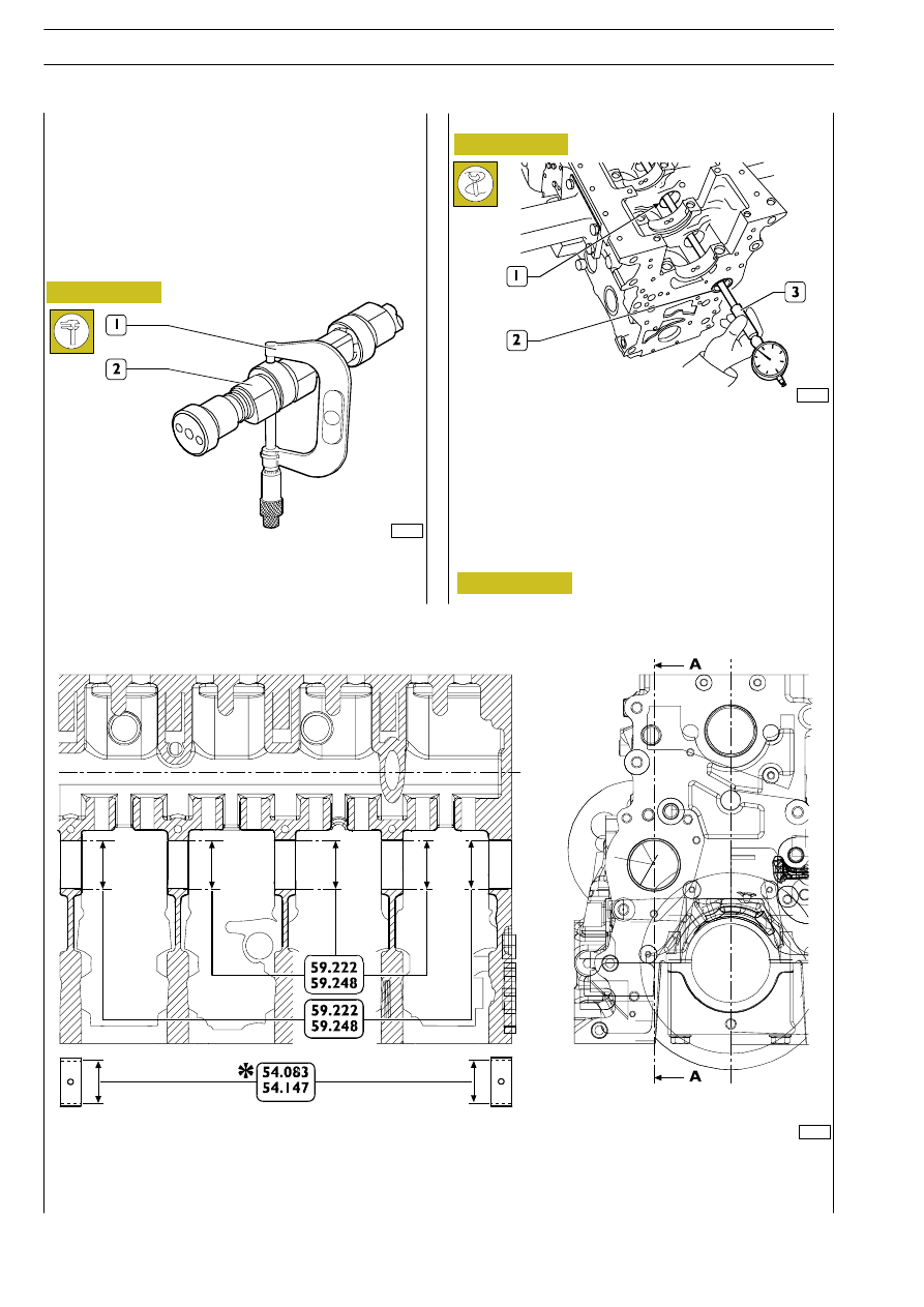
Check the camshaft (2) support pin diameter by means of a
micrometer (1) on two perpendicular surfaces.
The camshaft bushes (2) must result forced in their relevant
seats.
The inner surfaces must result without seizing and wearing
traces.
By means of a bore meter (3), measure the diameter of the
rear and front bushes (2) and intermediate seats (1) for
camshaft.
The
measurements
must
be
performed
on
two
perpendicular axes.
541213
BUSHES
MAIN DATA OF THE CAMSHAFT BUSHES AND RELEVANT SEATS
* Dimensions to be obtained after the bush driving
541211
Cam lift check and pin alignment
check
Position the shaft on counterpoints and, by means of a
centesimal gauge, located on the central support, check that
the alignment error is not higher than 0.04 mm: on the
contrary, replace the shaft. Then, check the cam lifting: it must
result of 6.045 mm for the exhaust ones and of 7.582 mm for
the suction ones; if you detect different values, replace the
shaft.
sec. A-A
E
URO
C
ARGO
T
ECTOR
12-26 t
50
ENGINE F4 AE 0481
Base - February 2003