Iveco Daily. Manual - part 420


  Index      Iveco     Iveco Daily - service repair manual 2004 year


Search            


Content   ..  418  419  420  421   ..


Iveco Daily. Manual - part 420


206

ELECTRIC/ELECTRONIC SYSTEM

D

AILY

Base - May 2004

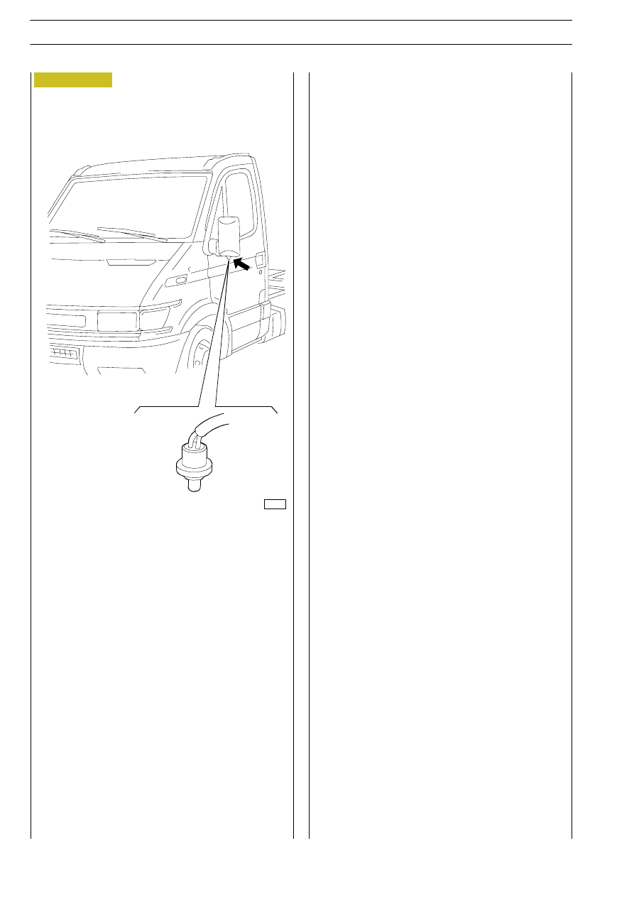
This is an NTC sensor on the left wing mirror (Figure 235) for

both types of drive.
The resistance at 25 °C is 10 kOhm.
Operating range between - 30 °C and + 50 °C.
It is connected to pin 6 connector B of the control unit.

OUTSIDE TEMPERATURE SENSOR

Figure 235

8665

ELECTRIC/ELECTRONIC SYSTEM

207

D

AILY

Inside temperature sensor

This is an NTC sensor located on the climate control module (Figure 237) between the two Re-circulation" and ECO"

switches.
It is ventilated and contains a motor/fan so that the temperature reading is not affected by stagnating air inside the dashboard

which is not realistic.
The resistance is 2.2 kOhm at 25 °C
Operating range between + 5 °C and + 45 °C
It is connected to pin 7 connector B of the control unit.
The motor A, fan B and sensor C are a single part and are connected to the wiring by a single connector at pin 12.

Pin

Function

1

Positive for motor

2

Negative for motor

3

Signal earth

4

Sensor signal for control unit (pin 7 connector B)

5

Positive from microswitch for MAX DEF" function to control unit (pin 6 connector A)

6

Ċ

7

Positive from ECO" switch to control unit (pin 5 connector A)

8

Earth

9

+15/A supply

10

+15/A supply

11

Negative for lighting pictograms

12

Positive from re-circulation switch to control unit (pin 12 connector A)

A

B

C

Figure 236

000260t

208

ELECTRIC/ELECTRONIC SYSTEM

D

AILY

Base - May 2004

This is an NTC sensor positioned inside the distributor unit

upstream of the air distribution ports to the various vents.
The resistance at 25 °C is 10 kOhm.
Operating range between 0 °C and - 80 °C
It is connected to pin 1 connector A of the control unit.

Evaporator temperature sensor

This is an NTC sensor positioned inside the distributor unit

and it is fitted directly on the evaporator. It causes switching

on (>4 °C) and switching off (>3.5Ă°C) of the compressor

electromagnetic clutch. The resistance at 25 °C is 10 kOhm.
Operating range between 0 °C and +25 °C.
It is connected to pin 3 connector B of the control unit.

Required temperature potentiometer

This  is  a  potentiometer  connected  to  the  required

temperature setting knob on the climate control panel.

It  detects  the  various  angular  positions  (Figure  238)  and

transmits a signal to the electronic control unit for a total of

fifteen different positions (one per degree centigrade) two of

which are the extremes HI" and LO" which correspond

respectively  to  a  request  for  the  coldest  and  warmest

positions.
It is supplied by the control unit at 5V.

Resistances R1 to R16 are approx. 700 Ohm.

Resistance R17 is approx. 1.1 Mohm

The total resistance R is approx. 11 kOhm.

It is connected to pin 2 and 9 connector A of the control unit.

REQUIRED TEMPERATURE SETTING KNOB

POTENTIOMETER POSITION DETECTION LAYOUT

A. Signal earth (ms7) - B. Signal to control unit pin 2 connector A - C. positive from control unit pin 9 connector A

A

C

B

Figure 237

Figure 238

000265t

000255t

ELECTRIC/ELECTRONIC SYSTEM

209

D

AILY

Ventilation control potentiometer

This is a potentiometer connected to the ventilation control

knob positioned on the climate control panel.
It  detects  the  various  angular  positions  (Figure  240)  and

transmits a signal to the electronic control unit for a total of

six different positions, four of which are manual flows (1, 2, 3,

and 4), one no air flow and one automatic (AUTO).
It is supplied by the control unit at 5 V.
The resistance R1 to R7 are approx. 1.5 kOhm.
Resistance R8 is approx. 1.1 Mohm.
The total resistance R is approx. 10.5 kOhm.
It is connected to pins 3 and 9 connector A of the control unit.

VENTILATION CONTROL KNOB

POTENTIOMETER POSITION DETECTION LAYOUT

A. Signal earth (ms7) - B. signal to control unit pin 3

connector A - C. Positive from control unit pin 9

connector A

A

C

B

Figure 239

Figure 240

000266t

000256t


Content   ..  418  419  420  421   ..