Iveco Daily. Manual - part 284


  Index      Iveco     Iveco Daily - service repair manual 2004 year


Search            


Content   ..  282  283  284  285   ..


Iveco Daily. Manual - part 284


!

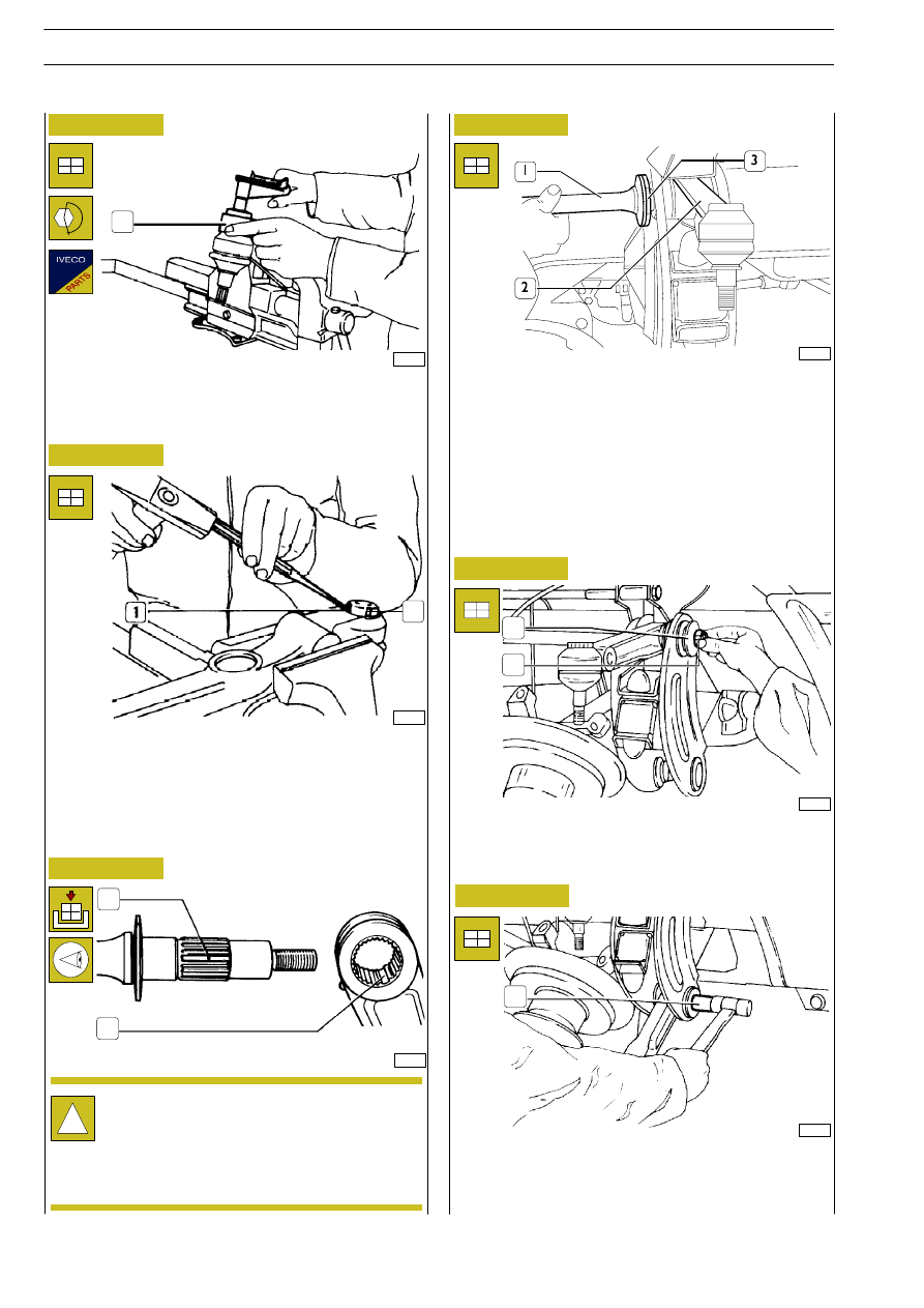
The letters AD - AS, printed in the back of torsion
bars, indicate respectively the right bar and the left
one.

Moreover the splined part has a double tooth (1) which, at
the reassembly, must correspond to the double spline (2) of
the upper lever.

With the tool No. 99357144 (1) fasten the ring nut (3,
Figure 50) to the prescribed torque.

19605

19604

19046

52370

Figure 51

Figure 52

Figure 53

Figure 54

Figure 55

Position the top suspension arm (2) in the cross member.
Then insert the torsion bar (1), with the washer (3), in the
cross member and in the suspension arm.

2

Bend a tongue of the safety lock (1) in the slot of the ring nut
(2).

Refitting

44674

Figure 56

Place the washer (1) and screw the nut (2) without tightening
it.

19052

Position the bottom suspension arm in the cross member
and insert the bushing (1).
Insert the screw with its washers and screw the nut without
tightening it.

1

1

2

1

2

1

38

FRONT MECHANICAL SUSPENSIONS

D

AILY

Base - May 2004

Refit the wheels, mount the nut guard and screw on the fixing
nuts; lower the vehicle, removing the stands..

Following the order shown in the figure, tighten the fixing
nuts to the required torque.

Then tighten the torsion bar fixing nuts to the required
torque and mount the safety split pins on them.

Tighten the nuts for the screws securing the top and bottom
tie rods to their respective levers to the required torque.

Fit the stabilizer bar (1) back onto the bottom screw stays (2)
with the clamps (3), taking care that the screws (4) go into
the slots in the stabilizer bar.
Complete fitting the suspension back on by mounting the
shock absorber.

Lubricate the grooved portion of the torsion bar (3).
Assemble the torsion bar (3) and the support (1) so that the
splines (2) of the toothed bush and of the torsion bar coincide.
Fix the support (1) to the chassis tightening the fastening
screw nuts to the prescribed torque.

74998

44675

44697

Figure 57

Figure 58

Figure 59

Figure 60

Connect the stub axle (3) to the link pins of the top (1) and
bottom (4) suspension arms. Tighten the fixing nuts (2) to
the required torque.

1

2

3

4

7768

Figure 61

44676

Refit the tie rods (4 and 7) to the suspension arms (1 and 6)
without tightening the nuts for the screws (3 and 5) to their
torque; connect the link pin (2) of the steering gear housing
tie rod to the lever of the stub axle and tighten the nut to the
required torque.

FRONT MECHANICAL SUSPENSIONS

39

D

AILY

Base - May 2004

If the value is different, act on the adjusting screw (1) as much
as you need it, but remember that, before acting on the
screw, it is necessary, to lift the vehicle with the hydraulic jack,
so that the wheels are lifted from the ground. This is
necessary if you do not want to damage the screw.

Once the vehicle has reached the right position, lock the
screw with the lock nut (2).

TORSION BAR PRE-LOADING CONTROL DIAGRAM

H = mm, distance from ground of the side frame upper

thread, measured as near as possible the suspension

connecting area

RSC = mm, loaded wheel radius

Ensure that the wheel pressure complies with the prescribed
one and check, with the suitable gauge, that the thread depth
of tyres is more or less the same on both wheels.
Measure on both sides of the vehicle, the distance from
ground (H) of the side frame upper thread, measured as near
as possible the suspension connecting area.
The height H must correspond to the value given in the table
below.

20986

74999

Figure 62

Figure 63

40

FRONT MECHANICAL SUSPENSIONS

D

AILY

Base - May 2004

HEIGHT OFF GROUND (H in millimetres) OF THE TOP EDGE OF THE CHASSIS FRAME IN RELATION TO THE
WEIGHT FOR MODELS 35C/40C/45C/50C WITH TORSION BAR DIAMETER 29 mm.

Weight on the front wheels

Tyres

Weight on the front wheels

(Kg)

195/75 R 16

6. 50 R 16

1200

610

629

1220

608

627

1240

606

625

1260

604

623

1280

603

622

1300

601

620

1320

599

618

1340

597

616

1360

596

615

1380

594

613

1400

592

611

1450

588

607

1500

584

602

1550

579

598

1600

575

593

1650

571

589

1700

566

585

1750

562

580

1800

558

576

1850

553

571

1900

549

567

75000

75001

Figure 64

Figure 65

528030

STABILIZER BAR

Removal

FRONT STABILISER BAR

Vehicles 35C - 40C - 45C - 50C

Unscrew the screws (2) fixing the half-brackets (3) and
remove the stabilizer bar (1) from the vehicle, recovering the
rubber plugs (4).

Check that the bushings and/or elastic elements are
not worn or deteriorated; if they are, replace the
relevant part.

500910

FRONT SHOCK ABSORBERS

Removal

Check that the bushings and/or elastic elements are
not worn or deteriorated; if they are, replace the
relevant part.

FRONT SHOCK ABSORBER

Vehicles 35C - 40C - 45C - 50C

Set the vehicle on level ground.
Lock the rear wheels with scotches, remove the wheel rim
guards and loosen the screws or nuts fixing the wheel.
Lift the front of the vehicle and rest the chassis frame on
supports.
Take out the screws or nuts fixing the wheel and remove
them with tool 99321024.
Unscrew the top and bottom bolts (2), then remove the
shock absorbers (1) from the vehicle.

Refitting

To fit it back on, perform the steps carried out for
removal in reverse order, keeping to the prescribed
tightening torques.

Using a suitable instrument, check the efficiency of the shock
absorbers.

Refitting

To fit it back on, perform the steps carried out for
removal in reverse order, keeping to the prescribed
tightening torques.

FRONT MECHANICAL SUSPENSIONS

41

D

AILY

Base - May 2004


Content   ..  282  283  284  285   ..