Iveco Daily. Manual - part 204
85918
85919
85917
6
TH
/5
TH
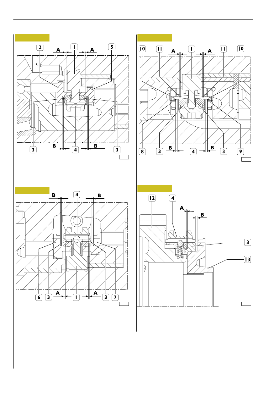
GEAR SYNCHRONISERS
A. synchronization reserve 6
th
/5
th
gear: 1
÷ 1,4 mm
B. 6
th
/5
th
release clearance: 0,3
÷ 0,7 mm
85916
3
TH
/4
TH
GEAR SYNCHRONISERS
A. synchronization reserve 1
st
/2
nd
gear: 1
÷ 1,4 mm
B. 1
st
/2
nd
release clearance: 0,3
÷ 0,7 mm
1
ST
/2
ND
GEAR SYNCHRONISERS
A. synchronization reserve 1
st
/2
nd
gear: 1,6
÷ 2,0 mm
B. 1
st
/2
nd
release clearance: 0,9
÷ 1,5 mm
REVERSE GEAR SYNCHRONISER
A. Synchronization reserve: 0.9
÷ 1,4 mm
B. release clearance: 0,35
÷ 0,85 mm
1. Hub - 2. 6
th
gear - 3. Synchronizer ring - 4. Sliding sleeve - 5.
th
gear cog-wheel - 6. 3
rd
gear cog-wheel -
7.
th
gear cog-wheel - 8. 2
nd
gear cog-wheel - 9. Reverse gear - 10. Middle ring - 11. Ring - 12. Reverse gear -
13. Reverse gear ring
Figure 77
Figure 78
Figure 79
Figure 80
72
6 S 300 TRANSMISSION
D
AILY
Base - May 2004