Iveco Daily. Manual - part 7
61983
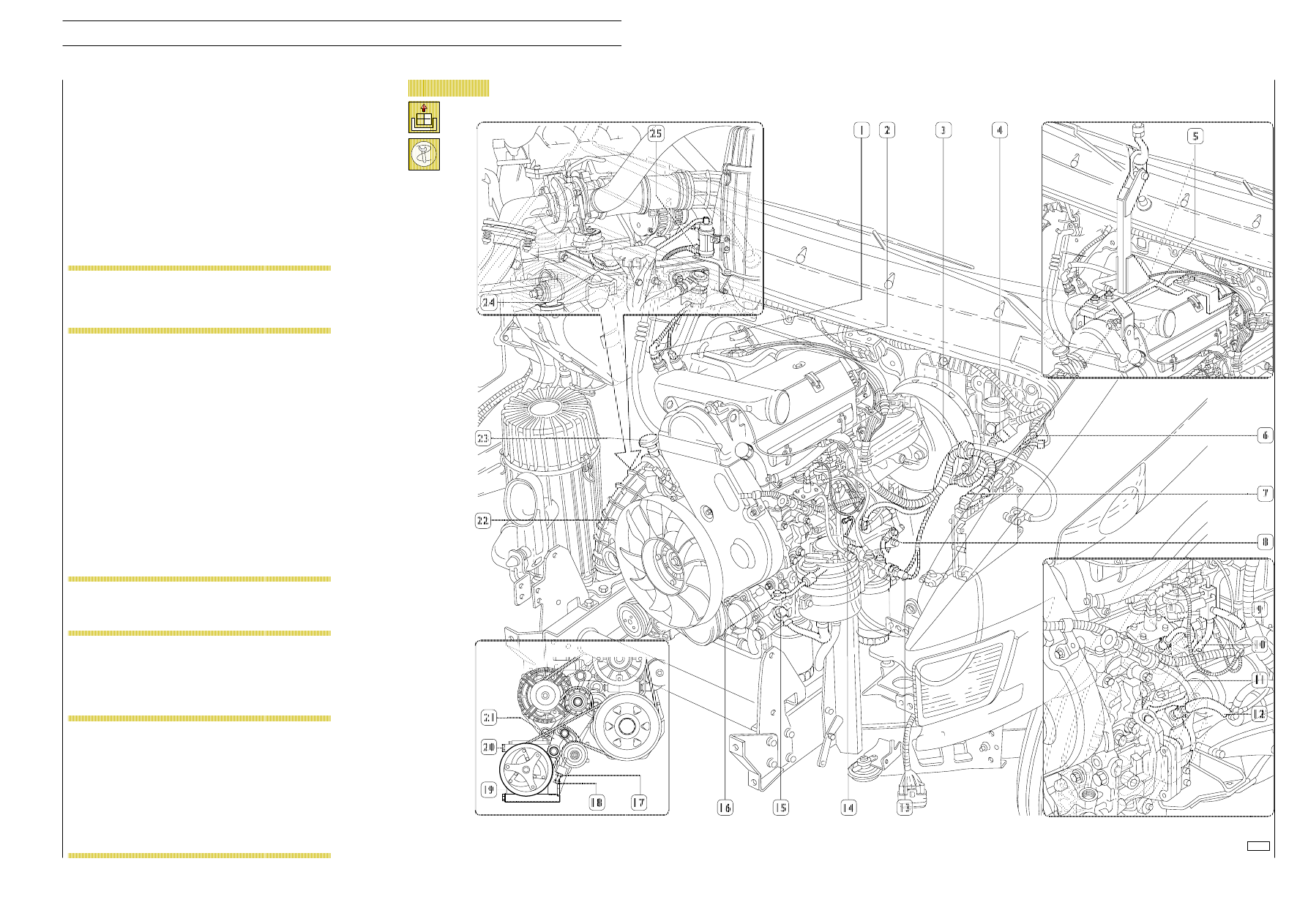
Figure 3
Disconnect the electrical connections of the engine cable:
- (4), from the fascia wiring;
- (6), from the chassis frame cable;
- (7), from the electronic control unit;
- (8), of the earthing cable on the engine;
- (14), from the low engine oil level indicator;
- (25) from turbosupercharger actuator control solenoid
valve (engine 8140.43N only);
- (13), from the diesel filter.
Disconnect the electrical connection (1) from the thermostart
glow plug.
Disconnect the electrical connection (2) from the thermostart
solenoid valve.
Unscrew the screws (3) to free the engine cable from the
body.
Disconnect the fuel pipe (11) from the high-pressure pump.
Disconnect the fuel recovery pipes (9 and 10).
Disconnect the pipe (12) from the vacuum pump.
Place a container under the power steering pump to recover
the oil from the system. Then disconnect the oil inlet and
outlet pipes (15 and 16).
Disconnect oil vapour piping (23) from flow control valve (for
EGR versions only).
Disconnect air intake duct (22) from turbosupercharger.
Disconnect pressure pipe (24) from turbosupercharger
actuator control solenoid valve (engine 8140.43N only).
Attach the rocker arm 99360550 (5) to the lifting hooks on
the engine. Hook it onto the hoist and put the engine slightly
under traction.
The remaining electrical connections of the engine
cable should be disconnected from the relative
electric components after removing the engine (see
Figure 5).
NOTE
Close the turbocharger air outlet appropriately to
prevent foreign bodies accidentally getting inside
and damaging it.
NOTE
Vehicles with air-conditioning in the cab should have
the compressor (20) disconnected as follows:
- loosen the nut (17);
- unscrew the tightener screw (18);
- remove the drive belt (21);
- take out the screws (19) and put the
compressor (20) back into the engine bay
without disconnecting it from the system pipes.
NOTE
ENGINES 8140
9
D
AILY
Base - May 2004