Index Iveco Iveco Daily Euro 4 - service repair manual 2006 year
Search
Content .. 262 263 264 265 ..
Iveco Daily Euro 4. Manual - part 264
140
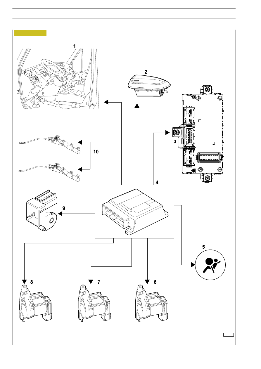
ELECTRIC/ELECTRONIC SYSTEM
D
AILY
E
URO
4
107679