Iveco Daily Euro 4. Manual - part 192
Turn up the spin switch (6) to the second speed and place the
balancing machine against the tyre.
While the wheel is being spun, it will be found that the
stroboscopic effect on the wheel will make the reference
mark appear stationary; the pointer of the instrument (1),
moving from the value zero, reaches a maximum value on the
scale and then returns to zero.
When the pointer has begun to fall back, withdraw the
balancing machine, turn off the spin-up switch (6) completely
and brake the motor by means of the brake lever (7).
The wheel continues to revolve due to inertia and the
reference mark made on the tyre moves; the point to which
the reference mark has moved should therefore be noted.
Read off from the instrument (1) the value shown by the
pointer, multiply it by 10, giving the value of the balance weight
to be fitted to the rim.
The front wheels can be balanced on the vehicle using the
electronic unit 99305037; this has the advantage of balancing
the wheel together with the other rotating masses.
The operation must be carried out as follows:
- Raise the front of the vehicle and make sure that the
wheels are free to rotate
- Position the imbalance detector (1) under the axle close
to the wheel being examined, arranging the height so that
the spin-up wheel of unit 99305037 (2) is in contact with
the tyre; position a support stand under the opposite side
of the axle and lower the hydraulic jack.
16998
Figure 3
Figure 4
23885
Figure 5
- Connect the cable (3) of the imbalance detector to unit
99305037
- Make a reference mark on the tyre by drawing a radial
mark with chalk or using a strip of gummed paper
- Turn switch (2) to the static balancing position and
sensitivity switch (4) to notch no. 5 on the graduated scale
- Turn on switch (5) for instrument light (1) and strobe
lamp switch (8).
- Turn the spin-up switch (6) of unit 99305037 to the first
speed position so as to make the wheel rotate.
16997
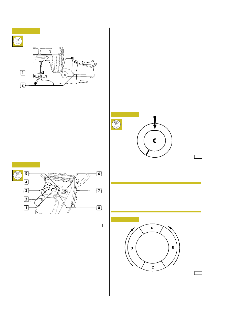
Fit the balance weight calculated in this way as shown in the
figure.
If during the test, the pointer of the instrument (1, Fig. 4)
remains in the green area of the box, the wheel is balanced.
To correct the residual imbalance, repeat the operations
already carried out as above; depending on the new reading
of the instrument (1, Fig. 4), refer to the diagram in the figure
and proceed as follows to adjust:
Figure 6
If the weight required to balance the wheel is more
than 60
÷ 80 grams, divide the weight in half and
position the two parts so formed with one half on
the inside and one half on the outside of the rim,
making sure that they are in the same position.
NOTE
8
WHEEL AND TYRES
D
AILY
E
URO
4
STATIC WHEEL BALANCING