Iveco Daily Euro 4. Manual - part 122
8
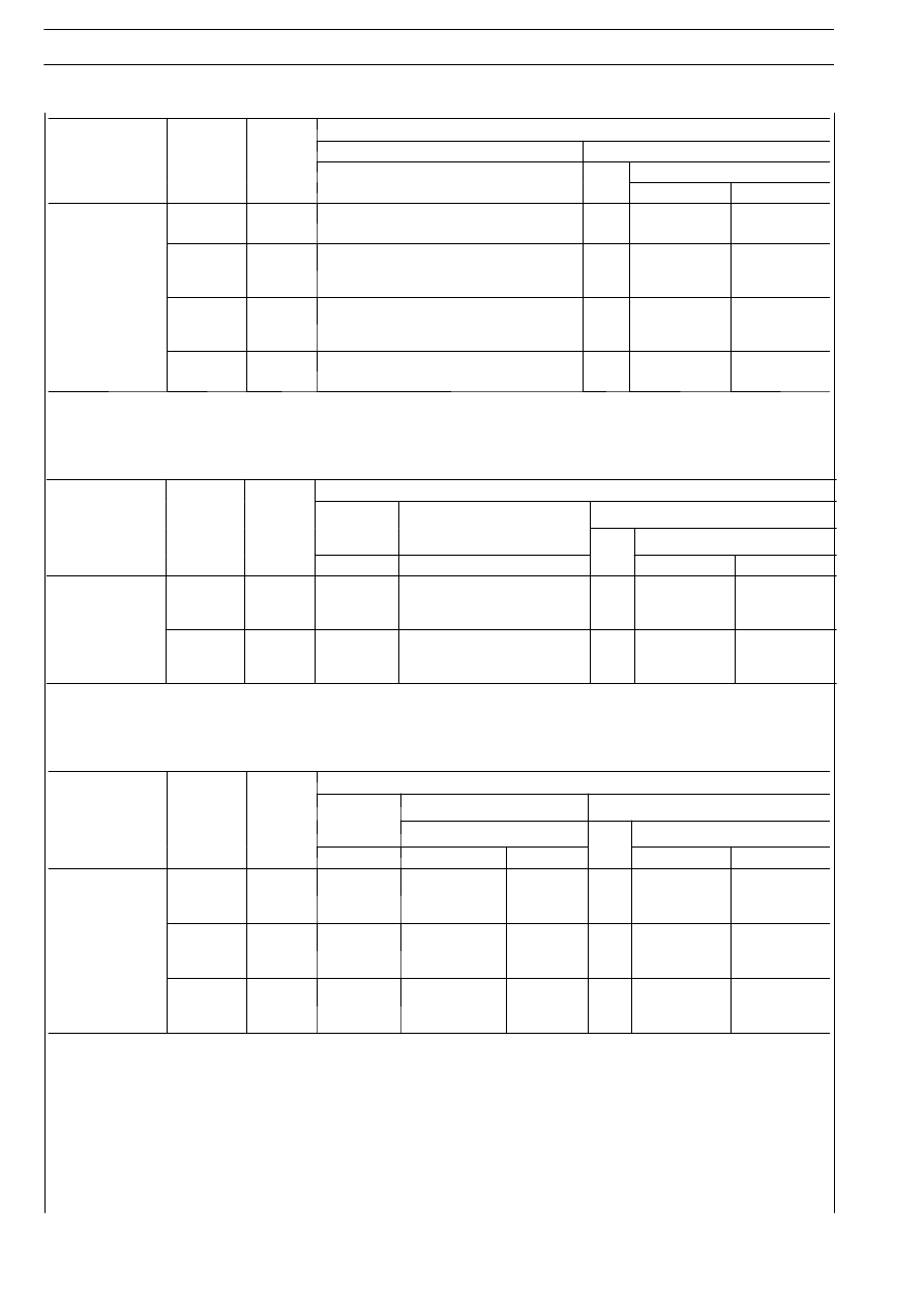
PROPELLER SHAFTS
D
AILY
E
URO
4
MODEL
VERSION
PITCH
Front shaft SENZA CODICE-4
Rear shaft SENZA CODICE-2
MODEL
VERSION
(mm)
L
L
1
L
L
L
1
GKN supply
DANA supply
VAN
3300
670
614
1630
÷ 1720
1630
÷ 1715
60C - 65C 15/18
CHASSI
CAB
3450
670
626
1780
÷ 1870
1790
÷ 1875
60C - 65C 15/18
CHASSI
CAB
3750
670
660
2075
÷ 2165
2085
÷ 2170
VAN
3950
670
995
2280
÷ 2370
2280
÷ 2365
Propeller shaft length in mm.
MODEL
VERSION
PITCH
Front shaft
SENZA CODIC
Central shaft
Rear shaft
MODEL
VERSION
PITCH
(mm)
SENZA CODIC
-4
Central shaft
SENZA CODICE-4
L
1
L
L
L
L
1
GKN supply
DANA supply
60C - 65C 15/18
CHASSI
CAB
4350
670
801
724
1885
÷ 1975
1885
÷ 1970
60C - 65C 15/18
CHASSI
CAB
4750
670
730
1065
2350
÷ 2440
2350
÷ 2435
Propeller shaft length in mm.
MODEL
VERSION
PITCH
Front shaft
SENZA CODIC
Central shaft SENZA CODICE
Rear shaft Figure 5.1.2
MODEL
VERSION
PITCH
(mm)
SENZA CODIC
-4
L
L
1
L
L
GKN supply
DANA supply
L
1
GKN supply
DANA supply
CHASSIS
COWL
3750
670
(S) 970
÷1070
-
-
(S) 825
÷925
-
60C - 65C 15/18
CHASSIS
COWL
4350
670
(S) 970
÷1070
-
-
(S) 1395
÷1495
-
CHASSIS
COWL
4750
670
(S) 1080
÷1180
-
408
-
(S) 1705
÷1790
(
S
) Vehicles with Telma retarder