Iveco Daily Euro 4. Manual - part 104


  Index      Iveco     Iveco Daily Euro 4 - service repair manual 2006 year


Search            


Content   ..  102  103  104  105   ..


Iveco Daily Euro 4. Manual - part 104


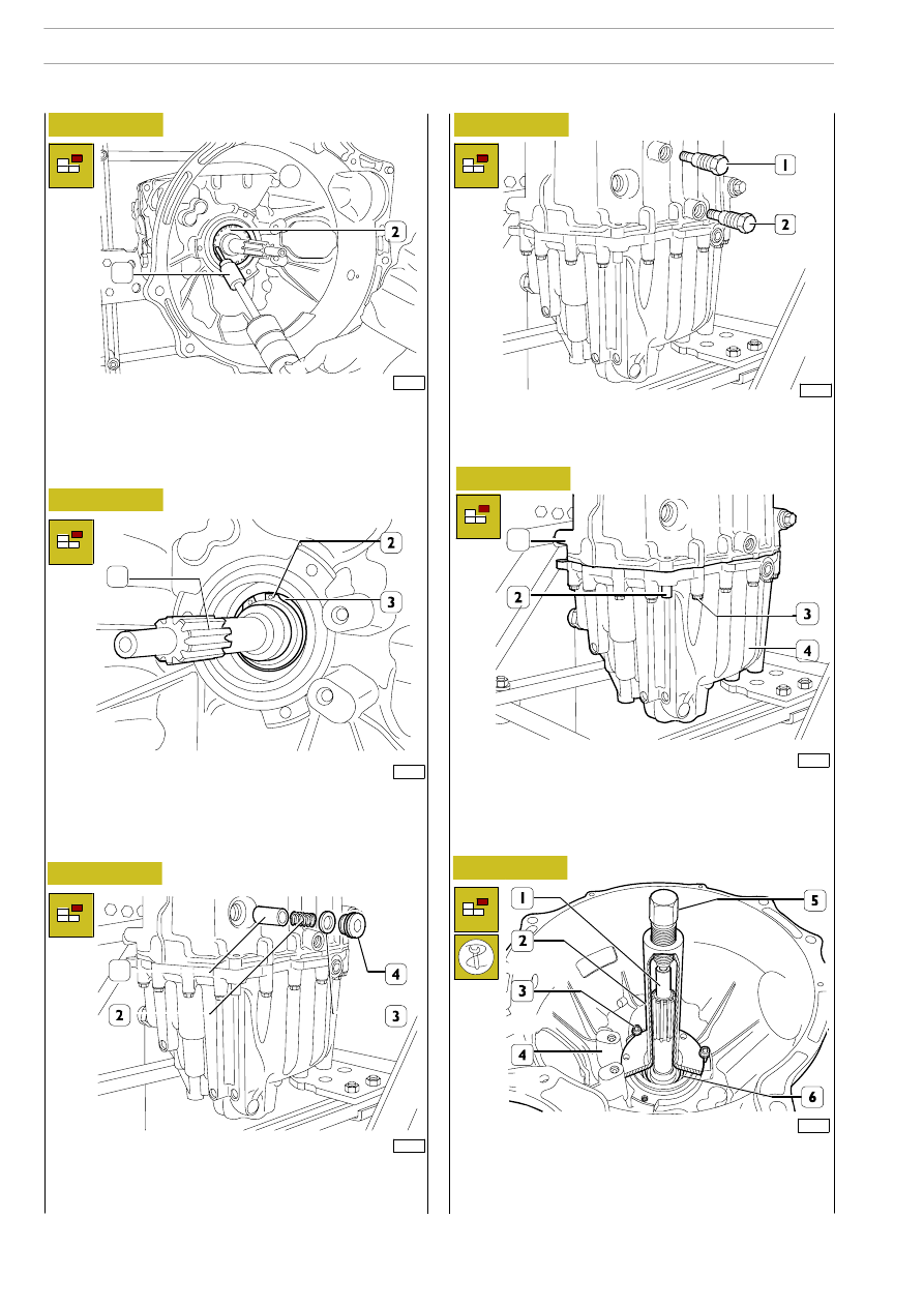
Fit the drive input shaft (1) with tool 99345003 (2) and
secure this onto the gearbox (4), with the screws (3); screw
down the screw (5) of tool (2) to extract the gearbox from
the bearing (6).

Perforate the o-ring (2) with a suitable hook and ram extractor
99340205 (1) and remove the o-ring from the transmission
box.

51930

51932

51931

51934

74957

Figure 41

Figure 42

Figure 43

Figure 44

Figure 45

Remove the circlip (2) retaining the front bearing (3) from the
input shaft (1).

Take out the plug (4) with the washer (3), and extract the
spring (2) and the push rod (1).

Push the two locating pins (2) downwards until taking them
out of the rear cover (4).
Remove the screws (3) securing the rear cover (4) to the
transmission (1).

90209

Remove the two fork knuckle pins (1) which control the 3

rd

— 4

th

speed and the two fork knuckle pins (2) which control

the 5

th

— 6

th

speed.

Figure 46

1

1

1

1

70

6 S 400 O.D. TRANSMISSION

D

AILY

E

URO

4

Mount the tool 99360522 (3) onto the rods (4, 5 and 6), on
the input shaft (1) and on the transmission shaft (9).
Secure the tool 99360522 (3) on the input shaft (1) with the
retaining ring (2) and with the screw (8) to the transmission
shaft (9).
Insert the part (13) of the bracket (11) into the reverse gear
(14) and tighten the screw (12).
Hook the tool 99360522 (3) onto the lift.

Apply the extractor composed of the bridge 99341004 (16)
and ties 99341012 (15) onto the rear cover (7).

51936

90211

90210

90212

90213

Figure 47

Figure 48

Figure 49

Figure 50

Figure 51

Drill the cups (2), screw a special screw into them.

Using the screw, extract the cups (2) from the rear cover (1).
Remove the springs (3) and pawls (4).

Remove the rod (1) controlling the 3

rd

/4

th

gear and the main

rod (2) from the rear cover (3).

Take out the screw (3) and remove the reverse gear shaft (1)
with the mounting (2) from the rear cover (4).

Remove the rod (1) from the rear cover (2).

Using the extractor screw and the lift on the main shaft (10),
remove the main shaft (10) from the rear ball bearing and ex-
tract the shaft-rod assembly from the rear cover (7).

In order not to damage the rear cover (7), place
special protections between it and the ties (15).

NOTE

1

6 S 400 O.D. TRANSMISSION

71

D

AILY

E

URO

4

Turn over the rear cover (4).

Take out the O-ring (6).

Using a suitable punch, remove the ball bearing (5). Remove
the tachograph sensor (7) and the reversing light switch (1)
with the washer (2) and extract the push rod (3).

Remove the screws (1) securing the plates (2).
Take out the plates (2).
Turn over the rear cover (4) and remove the bearing (3).

51951a

51944

Figure 52

Figure 53

Disassembling the rear cover bearings

51943

74960

Figure 54

Figure 55

Using universal extractor 99348004 (1), remove the outer
ring (2) of the transmission shaft bearing.

Using the percussion extractor 99340205 (1) and part
99348004 (2), extract the bushing with the ball bearings (3).

Figure 56

Clamp the primary shaft (6) in a vice.
Remove the rods (10 and 11) with the relevant forks. Remove
the forks (3 and 4) and the small blocks.

Remove the RM gear (4).
Remove the snap ring (8) and the tool 9936522 (9).
Remove the input shaft (7).

Support the secondary shaft (2), slacken the screw (1)
and remove the secondary shaft (2).

90214

1

1

72

6 S 400 O.D. TRANSMISSION

D

AILY

E

URO

4

51410

85945

Figure 57

Figure 58

Remove the screws (1) securing the plates (2).
Take out the plates (2).
Turn over the transmission. Using a suitable punch, remove
the ball bearing (3).

Remove the sliding sleeve (2) for engaging 5

th

- 6

th

gear from

the hub (1) and, taking care as the plugs (5) come out with the
balls (4) and springs (3), recover them.

Using the percussion extractor 99340205 (1) and part
99348004 (2), extract the roller bearing (4-3).

Mark the assembly position of each synchronizing de-
vice on the respective gear.

85944

Figure 59

Figure 60

Tighten the primary shaft (1) in a vice. Remove the
synchroniser ring (4) and the circlip (2). Remove the circlip (3)
from its housing.

Disassembling the main shaft

51948

NOTE

51946

Figure 61

Figure 62

Using universal extractor 99348004 (1), remove the outer
ring (2) of the transmission shaft bearing.

Disassembling the transmission bearings

Using the percussion extractor 99340205 (1) and part
99348004 (2), extract the bushing with the ball bearings (3).

74962

1

3

<<

6 S 400 O.D. TRANSMISSION

73

D

AILY

E

URO

4


Content   ..  102  103  104  105   ..