Iveco Daily Euro 4. Manual - part 91
18
5 S 300 TRANSMISSIONS
D
AILY
E
URO
4
TRANSMISSION
5 S 300
Type
Mechanical
Input torque
Nm
300
Weight
kg
44.6
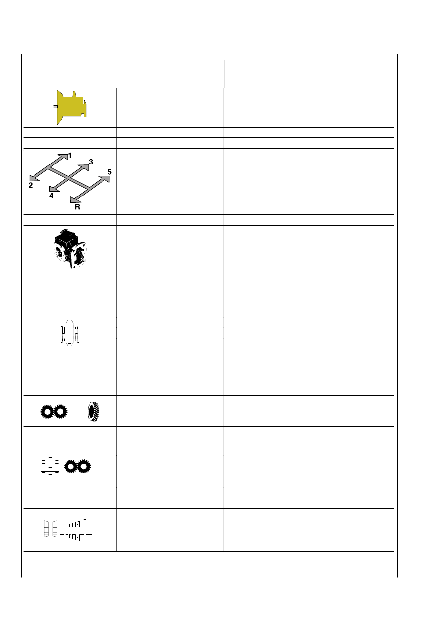
Speeds
5 forward speeds
1 reverse speed
Speed control
Mechanical
Power take-off
Optional
Speed engagement:
Forward speeds
- 5
th
/ 4
th /
3
nd
Single-cone synchronizer
- 2
nd
/ 1
st
Dual-cone synchronizer
Reverse speed
Rapid shift
Speed retention mechanism
Sliding sleeves retained by pawls and springs.
Gears
Helical-toothed constant mesh gears
Gear ratio
First
5.00
Second
2.62
Third
1.54
Fourth
1.00
Fifth
0.78
Reverse
4.58
Shaft bearings:
Main shaft
Straight roller bearing
watertight ball bearing
tapered roller