Iveco Daily Euro 4. Manual - part 24
75288
75309
75310
75311
Figure 112
Figure 113
Figure 114
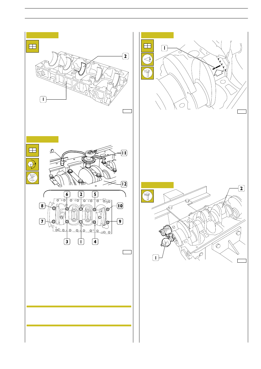
Thoroughly clean the bottom main bearing shells (2) and
mount them in the crankcase base (1)
Mount the crankcase base (12).
Tighten the screws in the sequence shown in the figure in
three steps:
- Step 1: with a torque wrench, to a torque of 50 Nm.
- Step 2: closing to an angle of 60
°.
- Step 3: closing to an angle of 60
°.
The end float is checked by setting a dial gauge (1) with a
magnetic base on the crankshaft (2) as shown in the figure.
The normal assembly clearance is 0.060 — 0.310 mm.
If you find the clearance to be greater than as required,
replace the rear main bearing shells carrying the thrust
bearings and repeat the clearance check between the
crankshaft pins and the main bearing shells.
If the end float of the crankshaft does not come within the
prescribed values, it is necessary to grind the crankshaft and
accordingly change the main bearing shells.
NOTE: The middle main bearing has half thrust washers
integrated in it, so it performs the function of a thrust bearing.
It is supplied as a spare part only with the normal shoulder
thickness.
α
Figure 115
- Remove the bottom crankcase.
The clearance between the main bearings and their
associated pins is measured by comparing the length of the
calibrated wire (1), at the point of greatest crushing, with the
graduated scale on the casing containing the calibrated wire.
The numbers on the scale indicate the clearance of the
coupling in millimetres, which must be 0.032
÷ 0.102 mm.
If the clearance is not as prescribed, replace the bearings and
repeat the check.
Checking crankshaft end float
Use tool 99395216 (11) for the angle closing.
NOTE
F1A ENGINE
83
D
AILY
E
URO