Engine Iveco Vector 8. Manual - part 13
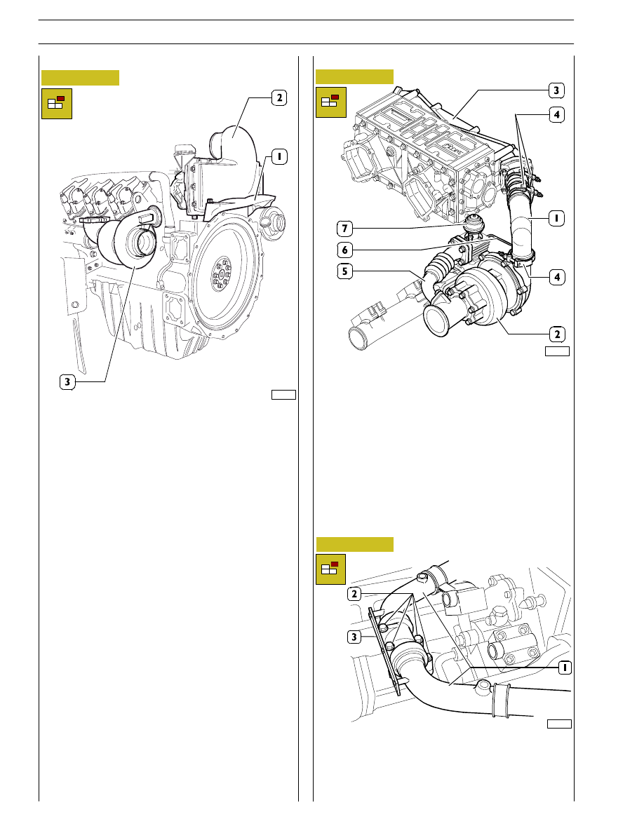
Figure 18
- Remove the bracket (1) for the flywheel and intercooler
casing (2).
- Undo the nuts fixing the turbocharger (3) to the exhaust
manifold.
- Then
repeat
this
procedure
for
the
second
turbo—blower.
103231
For G-DRIVE, DRAGON and GRIFFON applications
Figure 19
- Remove the manifold (1) between the turbo—blower (2)
and the intercooler (3), loosening the clamp (4) on the
manifold and on the turbo—blower .
- Remove the exhaust pipe (5) between the waste gate
valve (7) and the pipe of the turbo—blower.
- Remove the air pipe (6) between the turbo—blower and
the waste gate valve (7).
- Lastly, unscrew the nuts fixing the turbo—blower to the
exhaust manifold.
- Then remove the cooling pipes of the waste gate valve
(7) and detach it from the exhaust manifold.
- Then
repeat
this
procedure
for
the
second
turbo—blower.
Figure 20
- Disassemble the junction plate (3) of the cooling pipes
(1) and the three way fitting on the exchanger.
- Then disassemble the cooling pipes (1), the three way
fittings by loosening the screws (2) and the fitting on the
inlet of the main bearings.
89793
For all applications
83499
For SPRINKLER applications
16
SECTION 3 - INDUSTRIAL APPLICATION
VECTOR 8 ENGINES
Base - April 2006
Print P2D32V001E