Engines Iveco C10,C13, Cursor 10, Cursor 13. Manual - part 78
8
SECTION 2 - G-DRIVE APPLICATION
CURSOR ENGINES G-DRIVE
Base - May 2007
Type
F3A
Type
mm
1
X
X
1
2
X
X1
3.620 to 2.640
X
3
2
X
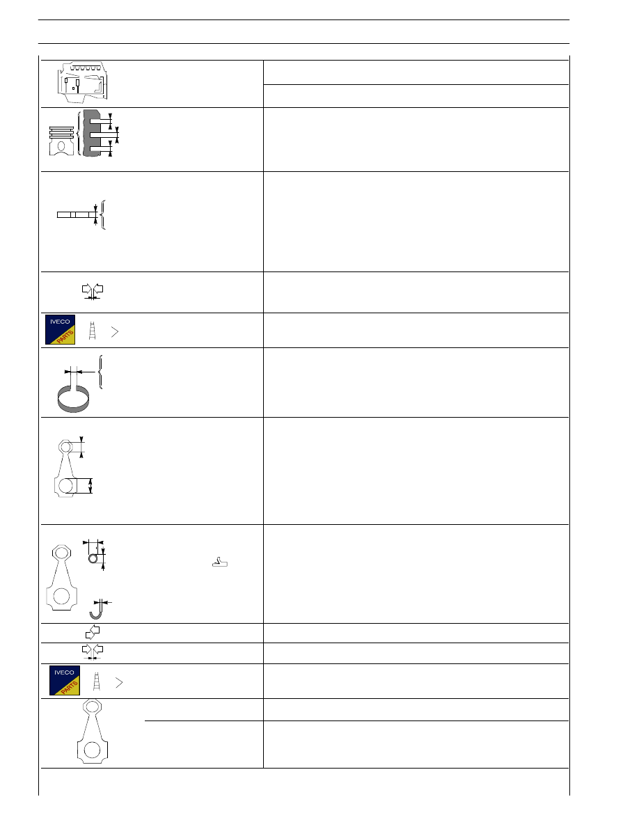
Piston ring grooves
X2
1.550 to 1.570
3
X
X3
4.020 to 4.040
Piston rings:
trapezoidal seal
S1
2.500
1
2
S
S
p
lune seal
S2
ill d
i
2.500
1.470 to 1.500
3
2
S
S
milled scraper ring
with slits and internal
spring
S3
3.970 to 3.990
spring
S3
3.970 to 3.990
1
0.120 to 0.140
Piston rings - grooves
2
0.050 to 0.100
3
0.030 to 0.070
Piston rings
-
X1
2
X
Piston ring end gap
in cylinder liners
3
2
X
X
X1
0.35 to 0.50
3
X
X2
0.60 to 0.75
X3
0.35 to 0.65
1
∅
Small end bush housing
Ø1
54.000 to 54.030
∅ 2
Big end bearing
housing
Ø2
1
Selection classes
2
3
{
87.000 to 87.030
87.000 to 87.010
87.011 to 87.020
87.021 to 87.030
∅4
Small end bush diameter
∅3
outside
∅4
54.085 to 54.110
∅3
inside
∅3
50.019 to 50.035
S
Big end bearing shell
S
Red
Green
Yellow D
1.970 to 1.980
1.981 to 1.990
1.991 to 2.000
Small end bush - housing
0.055 to 0.110
Piston pin - bush
0.019 to 0.041
Big end bearing
0.127 - 0.254 - 0.508
Connecting rod weight
A
g. 3973 to 4003
Connecting rod weight
A
g. 3973 to 4003
Class
B
g. 4004 to 4034
C
g. 4035 to 4065
D
Fitted in production only and not supplied as spares