Engines Iveco C10,C13, Cursor 10, Cursor 13. Manual - part 66
 

  Index      Iveco     Engines Iveco C10,C13, Cursor 10, Cursor 13 (CURSOR TIER 3 SERIES) - service repair manual 2007 year


Search            


Content   ..  64  65  66  67   ..


Engines Iveco C10,C13, Cursor 10, Cursor 13. Manual - part 66


Make sure the piston does show any trace of seizing, scoring,
cracking; replace as necessary.

60608

60607

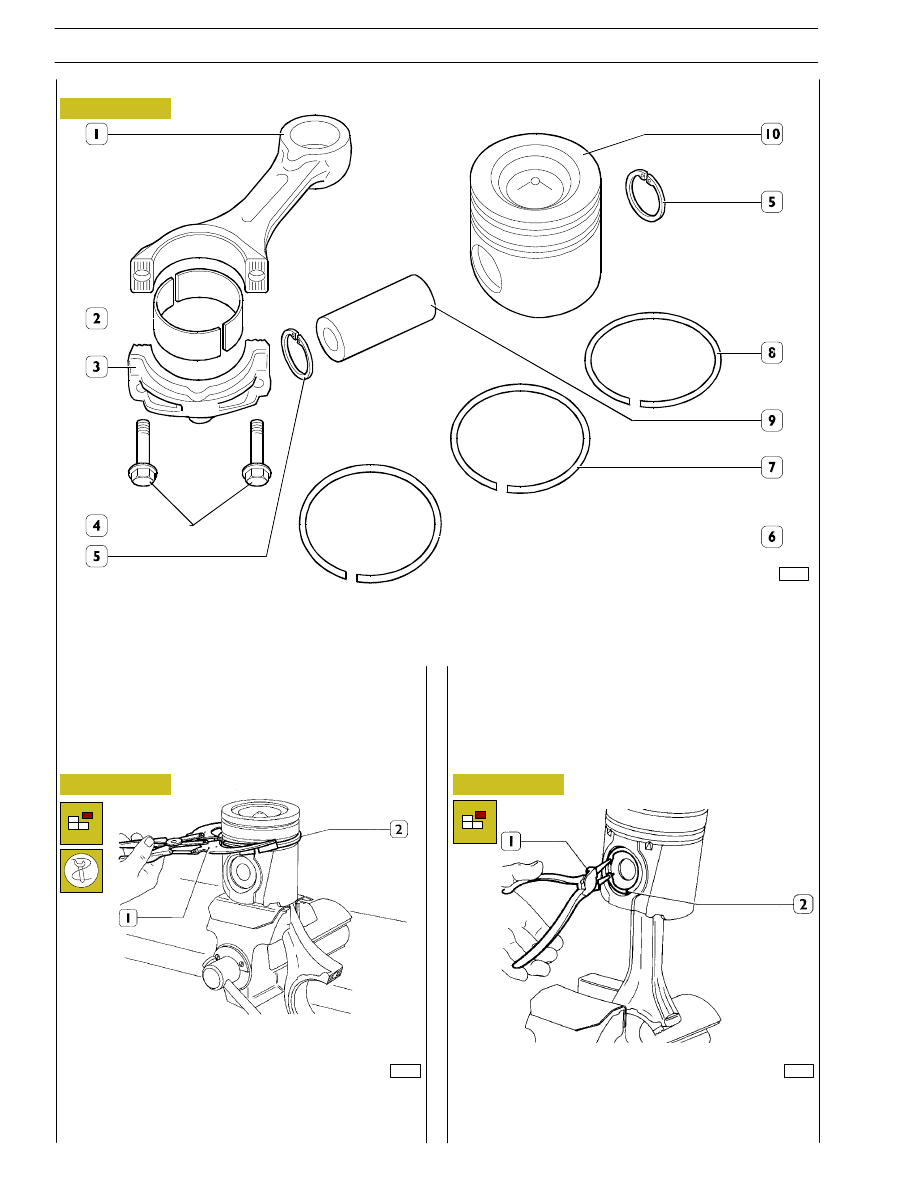
Figure 48

Figure 49

PISTON CONNECTING ROD ASSEMBLY

1. Connecting rod body - 2. Half bearings - 3. Connecting rod cap - 4. Cap fastening screws - 5. Split ring -

6. Scraper ring with spiral spring - 7. Bevel cut sealing ring - 8. Trapezoidal sealing ring - 9. Piston pin - 10. Piston.

Removal of the piston split rings (2) using the pliers 99360184
(1).

Removal

Pistons are equipped with three elastic rings: a sealing ring, a
trapezoidal ring and a scraper ring.

Pistons are grouped into classes A and B for diameter.

49024

Figure 50

Remove the piston pin split rings (2) using the round tipped
pliers (1).

PISTON CONNECTING ROD ASSEMBLY

28

SECTION 4 - OVERHAUL AND TECHNICAL SPECIFICATIONS

F3B CURSOR ENGINES

Base - May 2007

1

2

49025

32618

49026

Figure 51

Figure 52

Figure 53

Figure 54

Remove the piston pin (1).
If removal is difficult use the appropriate beater.

Measuring the diameter of the pistons

Measuring the gudgeon pin diameter (1) with a micrometer (2).

Conditions for correct gudgeon pin-piston
coupling

Lubricate the pin (1) and the relevant housing on the piston
hubs with engine oil; piston must be inserted with a slight
finger pressure and it should not come out by gravity.

71714

Using a micrometer (2), measure the diameter of the piston
(1) to determine the assembly clearance; the diameter has to
be measured at the value X shown:

SECTION 4 - OVERHAUL AND TECHNICAL SPECIFICATIONS

29

F3B CURSOR ENGINES

MAIN DATA OF THE PISTON, PISTON RINGS AND PIN

16552

3513

Figure 55

Figure 56

Check the thickness of the piston ring (2) with a micrometer
(1).

The seal (2) of the 1st slot has a V shape. The clearance ”X”
between the seal and its seat is measured by setting the
piston (1) with the ring in the cylinder liner (3) so that the
seal comes half out of the cylinder liner.

Piston rings

104292

60610

Check the clearance between the seals (2) and their seats on
the piston (1) with a feeler gauge (3).

36134

Using a feeler gauge (2), check the opening between the ends
of the seals (1) inserted in the cylinder liner (3).
If you find the distance between the ends is less than or
greater than as required, replace the piston rings.

Figure 57

Figure 58

Figure 59

30

SECTION 4 - OVERHAUL AND TECHNICAL SPECIFICATIONS

F3B CURSOR ENGINES

Base - May 2007

47957

71716

Figure 60

Figure 61

MAIN DATA OF THE BUSHING, CONNECTING ROD, PIN AND BEARING SHELLS

* Measurement to be made after driving in the bushing.

Connecting rod punch markings

Letter indicating the class of weight:

A

=

4661 to 4694 g.

B

=

4695 to 4728 g.

C

=

4729 to 4762 g.

Number indicating the selection of the diameter
of the big end bearing seat:

1

=

94.000 to 94.010 mm

2

=

94.011 to 94.020 mm

3

=

94.021 to 94.030 mm

Number indicating the selection of diameter
for the big end bearing housing:

1

2

3

Punched on the big end of the connecting rod are the data
relating to the section in classes relating to the connecting
rod seats and the weights.

On assembling the connecting rods, check
they are all of the same class of weight.

VIEW FROM “A”

54.000
54.030

54.085
54.110

50.019*
50.035*

49.994
50.000

1.970
2.000

87.000
87.030

Connecting rod

NOTE

SECTION 4 - OVERHAUL AND TECHNICAL SPECIFICATIONS

31

F3B CURSOR ENGINES


Content   ..  64  65  66  67   ..