Engines Iveco C10,C13, Cursor 10, Cursor 13. Manual - part 33


  Index      Iveco     Engines Iveco C10,C13, Cursor 10, Cursor 13 (CURSOR TIER 3 SERIES) - service repair manual 2007 year


Search            


Content   ..  31  32  33  34   ..


Engines Iveco C10,C13, Cursor 10, Cursor 13. Manual - part 33


60624

47585

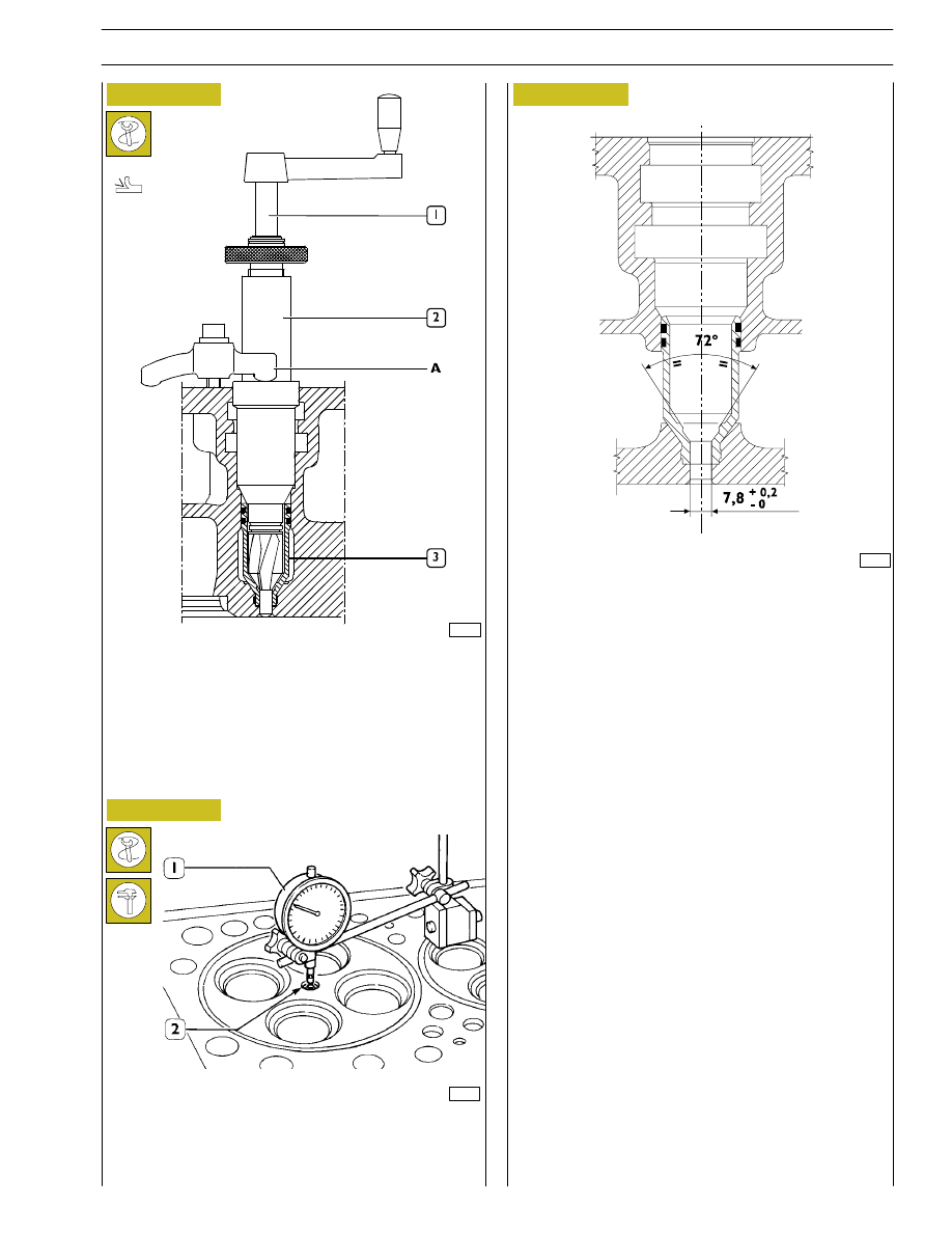
Check injector protrusion (2) with the dial gauge (1).
The protrusion must be 1.14 to 1.4 mm.

Checking injector protrusion

116812

INJECTOR CASE ASSEMBLY DIAGRAM

Figure 82

- Using grinder 99394041 (1-2), ream the injector seat in

the case (3), check the injector protrusion from the
cylinder head plane which must be 1.14 to 1.4 mm.

Figure 83

Figure 84

39

CURSOR ENGINES F3A

SECTION 4 - OVERHAUL AND TECHNICAL SPECIFICATIONS

Base - May 2007

86925

86934

TIMING CONTROL COMPONENT PARTS

1. Camshaft - 2. Bushing - 3. Pin - 4. Articulated rod -

5. Camshaft control gear - 6. Idler gear - 7. Twin idler gear

- 8. Drive shaft driving gear.

TIMING GEAR
Camshaft drive

Idler gear pin
Idler gear

87258

Twin intermediate gear pin
Twin idler gear

Replacing the bushings

Gear bushings shown on Figures 86 - 87 can be replaced
when they are worn. Put up the bushing, then bore it to
obtain the diameter shown on Figure 86 or Figure 87.

The bushing must be driven into the gear by following
the direction of the arrow and setting the latter to the
dimension shown on Figure 86 or Figure 87.

Rated assembling play between gear bushings and pins:
Figure 86 — 0.040

÷ 0.080 mm

Figure 87 — 0.045

÷ 0.085 mm.

Figure 85

Figure 86

Figure 87

NOTE

40

SECTION 4 - OVERHAUL AND TECHNICAL SPECIFICATIONS

CURSOR ENGINES F3A

Base - May 2007

47506

47505

47507

Figure 88

Figure 89

Figure 90

Camshaft
Checking cam lift and pin alignment

When the camshaft (4) is on the tailstock (1), check alignment of supporting pin (3) using a centesimal gauge (2); it must not
exceed 0.035 mm. If misalignment exceeds this value, replace the shaft.

In order to check installation clearance, measure bush inner diameter and camshaft pin (1) diameter; the real clearance is obtained
by their difference.
If clearance exceeds 0.150 mm, replace bushes and, if necessary, the camshaft.

Place the camshaft (4) on the tailstock (1) and check cam lift (3) using a centesimal gauge (2).

1

41

CURSOR ENGINES F3A

SECTION 4 - OVERHAUL AND TECHNICAL SPECIFICATIONS

Base - May 2007

The bush surfaces must not show any sign of seizing or
scoring; if they do replace them.

60626

116759

Figure 91

Figure 92

MAIN DATA - CAMSHAFT AND TOLERANCES

The surfaces of shaft supporting pin and cams must be extremely smooth; if you see any sign of seizing

or scoring, replace the shaft and the relative bushes.

MAIN DATA OF CAMSHAFT BUSHES AND RELEVANT HOUSINGS ON CYLINDER HEAD

* Bush inner diameter after installation

Bushings

Measure the bush inner diameters with a baremeter and replace
them, if the value measured exceeds the tolerance value.
To take down and fit back the bushes, use the proper tool
99360499.

Camshaft

42

SECTION 4 - OVERHAUL AND TECHNICAL SPECIFICATIONS

CURSOR ENGINES F3A

Base - May 2007

TOLERANCES

TOLERANCE CHARACTERISTIC

SYMBOL

ORIENTATION

Perpendicularity

POSITION

Concentricity or coaxial alignment

OSCILLATION

Circular oscillation

IMPORTANCE CLASS ASSIGNED TO PRODUCT CHARACTERISTICS

SYMBOL

CRITICAL

IMPORTANT

SECONDARY


Content   ..  31  32  33  34   ..