Engines Iveco C10,C13, Cursor 10, Cursor 13. Manual - part 32
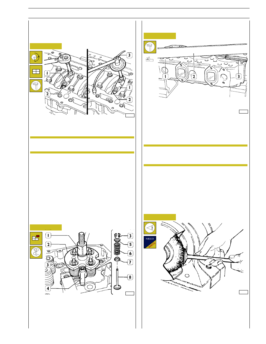
Mount the connecting rod caps (1) together with the bearing
shells. Tighten the screws (2) fixing the connecting rod caps
to a torque of 60 Nm (6 kgm). Using tool 99395216 (3),
further tighten the screws with an angle of 60
°.
CYLINDER HEAD
Before removing the cylinder head, check it is leakproof using
appropriate equipment. Replace the cylinder head if there is
any leakage.
47594
47583
36159
48625
Figure 69
Figure 70
Figure 71
Figure 72
Removing valves
Install and fix tool 99360261 (2) with bracket (4); tighten by
lever (1) until cotters are removed (3); remove the tool (2)
and the upper plate (5), the spring (6) and the lower plate (7).
Repeat the operation on all the valves.
Turn the cylinder head upside down and remove the valves (8).
The planarity (1) is checked using a ruler (2) and a thikness
gauge (3). If deformations exist, surface the head using proper
surface grinder; the maximum amount of material to be
removed is 0.3 mm.
Removing deposits and checking the valves
Remove carbon deposits using the metal brush supplied.
Check that the valves show no signs of seizure or cracking.
Check the diameter of the valve stem using a micrometer
(see Figure 73) and replace if necessary.
To check the clearance proceed as follows.
Connect the connecting rods to the relative main journals,
place a length of calibrated wire on the latter.
α
Checking the planarity of the head on the
cylinder block
(Demonstration)
After this process, you need to check the valve
recessing and injector protrusion.
Remove the caps and determine the clearance by comparing
the width of the calibrated wire with the graduated scale on
the case containing the calibrated wire.
Definitive assembly: check the diameter of screw threading
(2) it must not be less than 13.4mm along the entire length,
otherwise the screw is to be replaced; lubricate the pins and
bearings of the connecting rod; tighten the screws (2) as
described above.
The thread of the screws (2), before assembly, has
to be lubricated with engine oil.
Checking crankpin assembly clearance
NOTE
NOTE
35
CURSOR ENGINES F3A
SECTION 4 - OVERHAUL AND TECHNICAL SPECIFICATIONS
Base - May 2007