Engines Iveco C87 / Cursor 87. Manual - part 11
114260
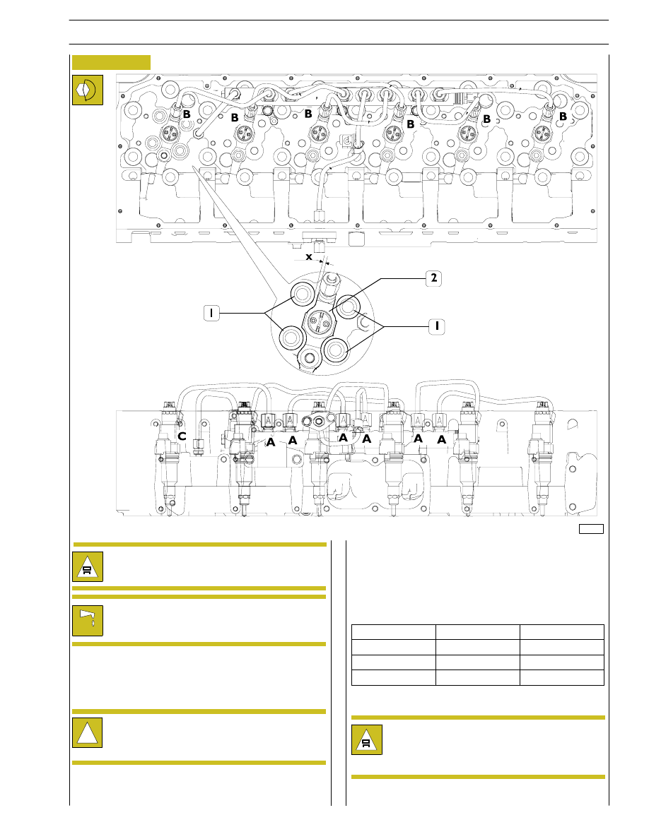
Figure 32
3.
Install pipes on rail and lock fittings by hand.
4.
Lock rail to cylinder head retaining screws at required
torque.
The previously removed pipes ca no longer be refit
and must be replaced.
After fitting the high-pressure pipelines, during the
following 20 hours of work, frequently check engine
oil level (IT MUST NOT INCREASE).
1.
Install rail on cylinder head and lock retaining screws by
hand.
2.
Install injectors in correct position and lock to required
torque.
!
Check that the injectors (2) are equidistant from the
springs (1). Distance ”X” which separates them
should always be the same.
5.
Fit pipes on injectors and head locking fittings by hand.
6.
Lock fittings on rail (A, C) at required torque .
7.
Lock fittings on injectors and head (B, C) at required
torque.
The previously removed pipes ca no longer be refit
and must be replaced.
SECTION 3 - INDUSTRIAL APPLICATION
13
F2C CURSOR ENGINES
TYPE
DESCRIPTION
LOCK TORQUE
A
M18 x 1.5
40
± 2 Nm
B
M14 x 1.5
35
± 2 Nm
C
M16 x 1.5
40
± 2 Nm