Engines Iveco N45, N67. Manual - part 16
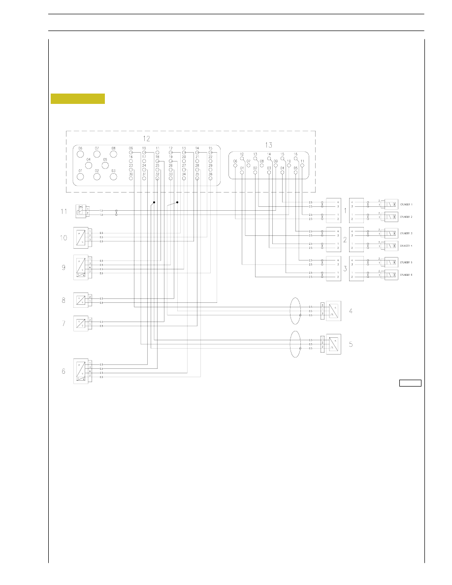
Figure 98
1. Injectors for cylinders 1-2 - 2 Injectors for cylinders 3-4 - 3. Injectors for cylinders 5-6 - 4. Engine rpm sensor -
5. Timing sensor - 6. Engine oil pressure and temperature sensor - 7. Fuel temperature sensor -
8. Coolant temperature sensor - 9. Air temperature and pressure sensor - 10. Rail temperature and pressure sensor -
11. Pressure regulator - 12. Connector C EDC control unit (signal) - 13. Connector A EDC control unit (power).
Cable on engine
All the components described below refer to the engine cable in question, therefore the connections to the pins are a preliminary
version, in other words at the approval stage.
0051064t
SECTION 3 - DUTY-INDUSTRIAL APPLICATION
35
F4HE NEF ENGINES
Print P2D32N003GB
Base - February 2006