Engines Iveco N45, N67. Manual - part 4
70484
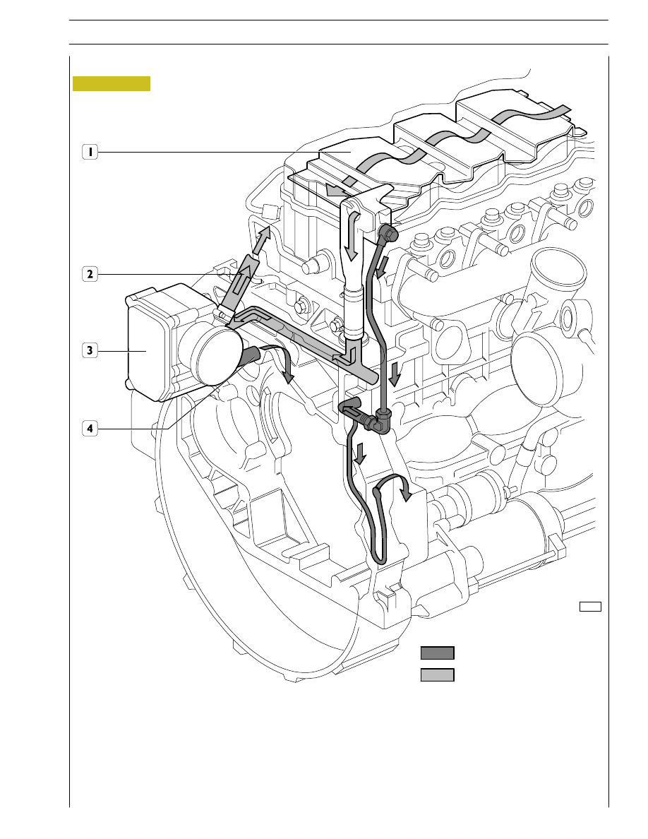
Figure 3
1. Pre-separator - 2. Exhaust to the outside (temporary) - 3. Filter - 4. Return to engine.
The tappet cover houses the pre-separator (1), whose shape and position determines an increase in oil vapour outlet speed and
condenses a part of vapours at the same time.
Condensate oil returns to the oil sump whereas the residual vapours are ducted, collected and filtered in the blow-by (3).
In the blow-by (3), part of the vapours condense and return to the oil sump whereas the remaining part is put into cycle again
through pipe (2).
Oil condensate
Oil vapours
OIL VAPOUR RECYCLING
SECTION 1 - GENERAL SPECIFICATIONS
7