Isuzu Amigo / Axiom / Trooper / Rodeo / VehiCross. Manual - part 614


  Index      Isuzu     Isuzu Amigo / Axiom / Trooper / Rodeo / VehiCross - service repair manual 1999-2002 year


Search            


Content   ..  612  613  614  615   ..


Isuzu Amigo / Axiom / Trooper / Rodeo / VehiCross. Manual - part 614


4A2–38 DIFFERENTIAL (REAR)
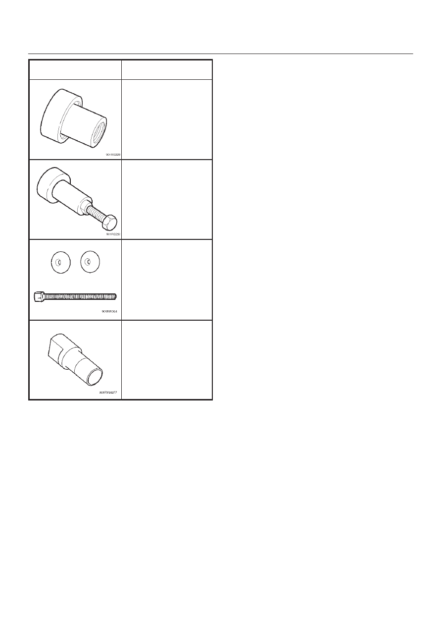
ILLUSTRATION

TOOL NO.

TOOL NAME

J–42829

Installer; Side bearing

J–39602

Remover; Outer bearing

J–39858

Clutch pack unloading

tool kit Includes

J–34174–1/J–34174–2

Screw cap and Cap

J–22342–15

Forcing screw

J–44450

Side gear holder

4B1–1

DRIVE LINE CONTROL SYSTEM (SHIFT ON THE FLY)

TROOPER

DRIVELINE/AXLE

DRIVELINE CONTROL SYSTEM (SHIFT ON THE FLY)

CONTENTS

Service Precaution

4B1–1

. . . . . . . . . . . . . . . . . . . . . . 

Shift On The Fly System

4B1–2

. . . . . . . . . . . . . . . . . 

Outline of Shift on The Fly System

4B1–2

. . . . . . . . . 

Functions of Indicator Lamp

4B1–6

. . . . . . . . . . . . . . 

Diagnosis

4B1–7

. . . . . . . . . . . . . . . . . . . . . . . . . . . . . . 

Front Axle Diagnosis

4B1–17

. . . . . . . . . . . . . . . . . . . . . 

Shift On The Fly Vacuum Piping And
 Electric Equipment

4B1–19

. . . . . . . . . . . . . . . . . . . . . . 

Vacuum piping diagram

4B1–19

. . . . . . . . . . . . . . . . . . 

Inspection And Repair

4B1–20

. . . . . . . . . . . . . . . . . . . 

4WD Control Unit

4B1–23

. . . . . . . . . . . . . . . . . . . . . . . 

4WD Control Unit Associated Parts

4B1–23

. . . . . . 

Removal

4B1–24

. . . . . . . . . . . . . . . . . . . . . . . . . . . . . 

Installation

4B1–24

. . . . . . . . . . . . . . . . . . . . . . . . . . . . 

Service Precaution

WARNING: THIS VEHICLE HAS A SUPPLEMENTAL
RESTRAINT SYSTEM (SRS). REFER TO THE SRS
COMPONENT AND WIRING LOCATION VIEW IN
ORDER TO DETERMINE WHETHER YOU ARE
PERFORMING SERVICE ON OR NEAR THE SRS
COMPONENTS OR THE SRS WIRING. WHEN YOU
ARE PERFORMING SERVICE ON OR NEAR THE SRS
COMPONENTS OR THE SRS WIRING, REFER TO
THE SRS SERVICE INFORMATION. FAILURE TO
FOLLOW WARNINGS COULD RESULT IN POSSIBLE
AIR BAG DEPLOYMENT, PERSONAL INJURY, OR
OTHERWISE UNNEEDED SRS SYSTEM REPAIRS.

CAUTION: Always use the correct fastener in the
proper location. When you replace a fastener, use
ONLY the exact part number for that application.
ISUZU will call out those fasteners that require a
replacement after removal. ISUZU will also call out
the fasteners that require thread lockers or thread
sealant. UNLESS OTHERWISE SPECIFIED, do not
use supplemental coatings (Paints, greases, or other
corrosion inhibitors) on threaded fasteners or
fastener joint interfaces. Generally, such coatings
adversely affect the fastener torque and the joint
clamping force, and may damage the fastener. When
you install fasteners, use the correct tightening
sequence and specifications. Following these
instructions can help you avoid damage to parts and
systems.

SECTION

4B1–2

DRIVE LINE CONTROL SYSTEM (SHIFT ON THE FLY)

Shift On The Fly System

Outline of Shift on The Fly System

The shift on the fly system switches between 2 wheel
drive (2WD) and 4 wheel drive (4WD)  electrically by
driver’s pressing the 4WD switch (push button type) on
instrument panel.
This system controls below operations. (Shifting between
“4H” and “4L” must be performed by transfer control lever
on the floor.)

1. Shifting the transfer front output gear (Connecting to,

and disconnecting from, front propeller shaft by motor
actuator).

2. Retrial of shifting the transfer front output gear.
3. Connecting front wheels to, and disconnecting them

from, the front axles by vacuum actuator.

4. Indicator on instrument panel.
5. 4WD out signal to other Electronic Hydraulic Control

Unit.

System Diagrams

412RX003

4B1–3

DRIVE LINE CONTROL SYSTEM (SHIFT ON THE FLY)

Normal Operation

The motor actuator mounted on transfer rear case is
driven by signal from 4WD switch on instrument panel.
After complete the connecting transfer front output gear
to, or disconnecting it from, front propeller shaft, condition

of the transfer position switch changes.  The vacuum
solenoid valve (VSV) is driven by the signal from transfer
position switch and the vacuum actuator connects front
wheels to, or disconnect them from, front axles.

Time Chart of Shifting Under Normal Condition

F04RW002


Content   ..  612  613  614  615   ..