Content .. 1354 1355 1356 1357 ..
Isuzu Amigo / Axiom / Trooper / Rodeo / VehiCross. Manual - part 1356
6A–28
ENGINE MECHANICAL (6VD1 3.2L)
Installation
NOTE: For correct belt installation, the letter on the belt
must be able to be read as viewed from the front of the
vehicle.
014RW005
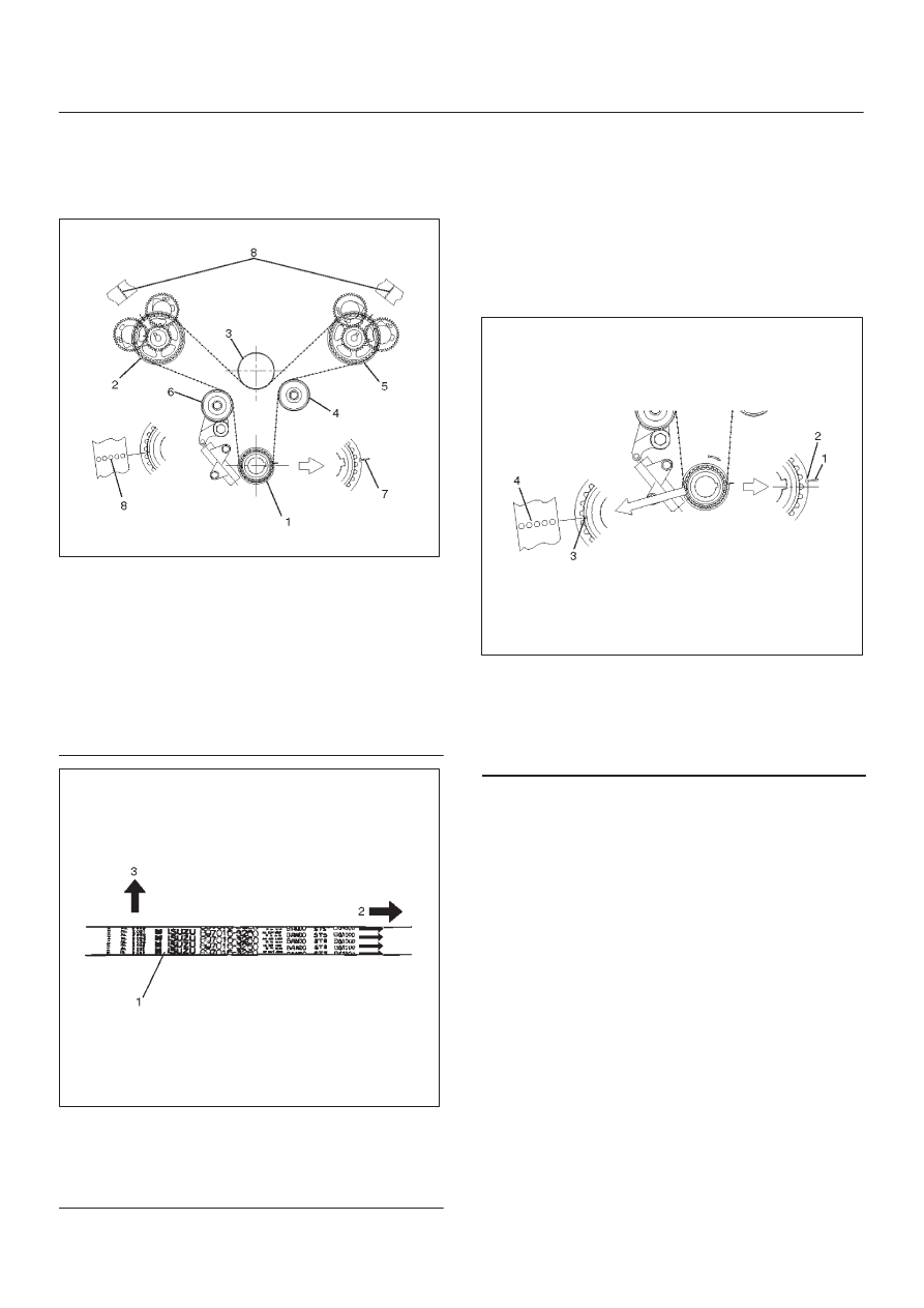
Legend
(1) Crankshaft Timing Pulley
(2) RH Bank Camshaft Drive Gear Pulley
(3) Water Pump Pulley
(4) Idle Pulley
(5) LH Bank Camshaft Drive Gear Pulley
(6) Tension Pulley
(7) Alignment Mark on Oil Pump.
(8) Alignment Mark on Timing Belt
014RW006
Legend
(1) Timing Belt
(2) Engine Rotation Direction
(3) Cylinder Head Side
1. Install timing belt.
1. Align groove of crankshaft timing pulley (2) with
mark on oil pump (1).
Align the mark on the crankshaft timing pulley (3)
with alignment mark (white dotted line) on the tim-
ing belt (4).
Secure the belt with a double clip or equivalent
clip.
NOTE: When timing marks are aligned, No.2 piston will
be on Top Dead Center.
014RW003
Legend
(1) Alignment Mark on Oil Pump
(2) Groove on Crankshaft Timing Pulley
(3) Alignment Mark on Crankshaft Timing Pulley
(4) Alignment Mark on Timing Belt