Isuzu Amigo / Axiom / Trooper / Rodeo / VehiCross. Manual - part 132
4C–28
DRIVE SHAFT SYSTEM
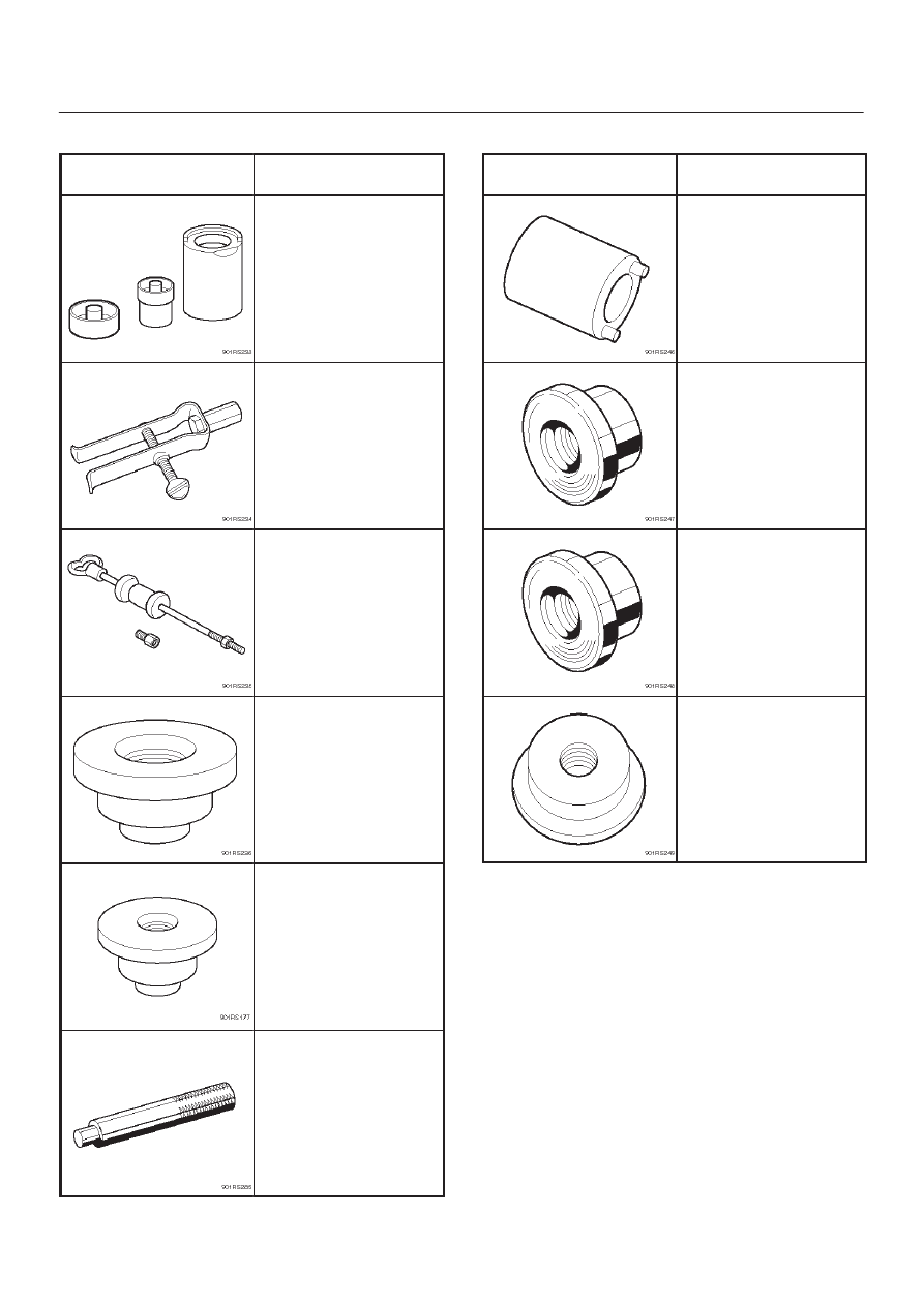
Special Tools
ILLUSTRATION
TOOL NO.
TOOL NAME
J–39378
Remover and Installer;
Front Axle mount
bushing
J– 26941
Remover; Bearing
needle
J–2619–01
Hammer; Sliding
J–41693
Installer; Oil seal
J–41694
Installer; Bearing needle
J–8092
Grip
ILLUSTRATION
TOOL NO.
TOOL NAME
J–36827
Wrench; Hub nut
J–36829
Installer; Inner bearing
J–36828
Installer; Outer bearing
J–36830
Installer; Oil seal