Isuzu Amigo / Axiom / Trooper / Rodeo / VehiCross. Manual - part 129


  Index      Isuzu     Isuzu Amigo / Axiom / Trooper / Rodeo / VehiCross - service repair manual 1999-2002 year


Search            


Content   ..  127  128  129  130   ..


Isuzu Amigo / Axiom / Trooper / Rodeo / VehiCross. Manual - part 129


4C–16

DRIVE SHAFT SYSTEM

7. Remove ball retainer, ball guide and bellows.
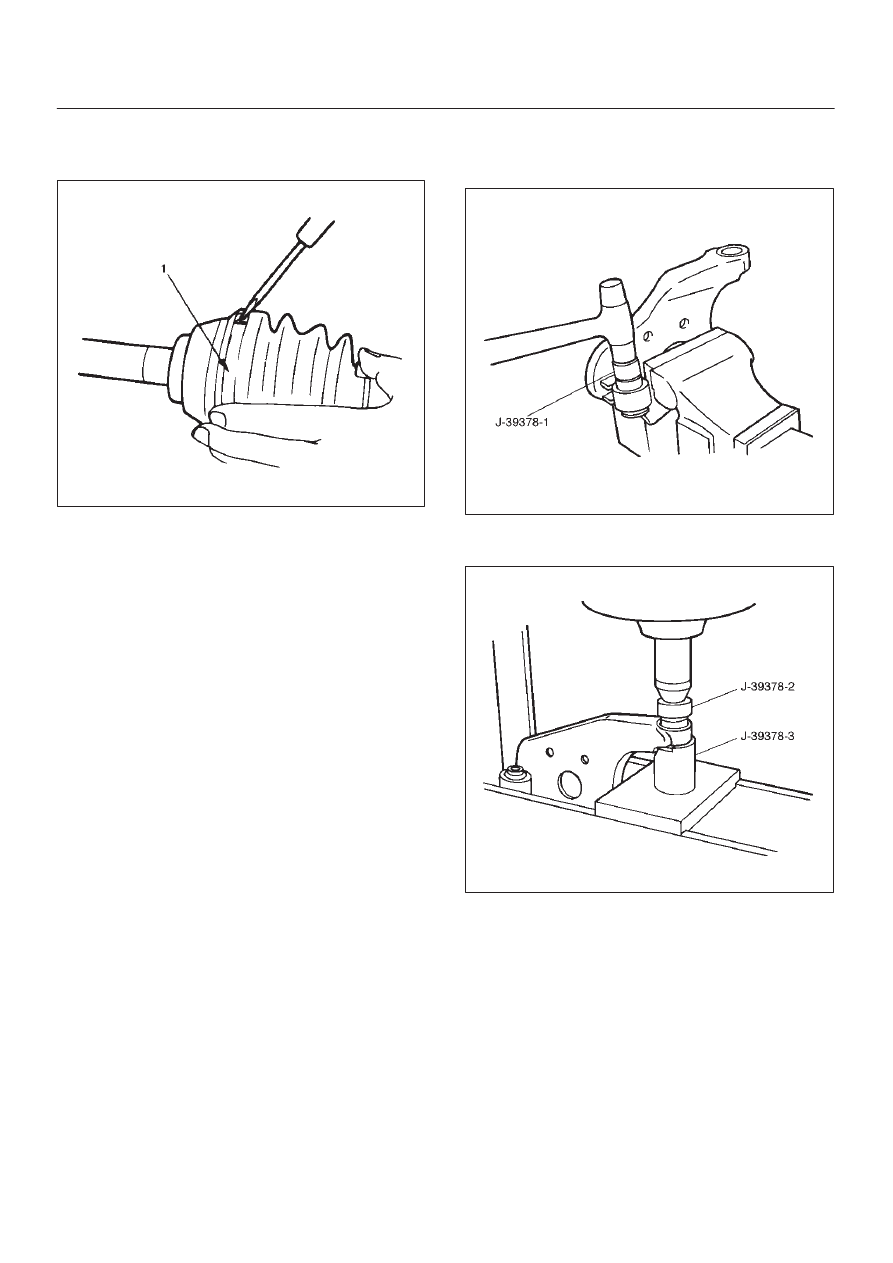
8. Raise the hooked end of the band with a screwdriver

or equivalent.

412RS014

9. Remove band(1).

10. Remove bellows.

11. Remove dust seal.

12. Remove BJ shaft assembly.
13. Remove the mounting bracket fixing bolts, and then

remove DOJ case assembly  from the axle case.

14. Remove snap ring and bearing.
15. Remove snap ring and oil seal.
16. Remove bracket.

Inspection And Repair

Make necessary correction or parts replacement if wear,
damage, corrosion or any other abnormal condition are
found through inspection.
Check the following parts.

1. Drive shaft joint assembly
2. DOJ case, ball, ball guide, ball retainer
3. Bellows
4. Bearing
5. Dust seal, oil seal

Bushing Replacement

D

Remove the bushings using a remover J–39378–1
and hammer.

412RS015

D

By using installer J–39378–2 and base J–39378–3,
press fit the bushings into the bracket.

412RS016

4C–17

DRIVE SHAFT SYSTEM

Reassembly

1. Install DOJ case to bracket.
2. Install oil seal  and fix snap ring.
3. Install bearing and fix snap ring.
4. Install bracket to axle case. Tighten the bracket bolt to

the specified torque.

Torque: 116 N·m (85 lb ft)

5. Apply 150g of the specified grease in BJ.
6. Install dust seal.
7. Apply a thin coat of grease to the shaft for smooth

installation then install bellows.

8. Install band. Note the setting direction.  After

installation, check that the bellows is free from
distortion.

412RS017

9. Install another bellows and fix band.

10. Install the ball guide with the smaller diameter side

ahead onto the shaft.

11. Install ball retainer.

12. Using snap ring pliers, install the snap ring (1)

securing the ball retainer to the shaft.

412RS013

13. Align the track on the ball (1) retainer with the window

in the cage, and install the six balls into position.

412RS018

14. Pack 150g of the specified grease in DOJ case, then

install drive shaft joint assembly. After reassembly,
move the DOJ longitudinally several times to get to fit.

4C–18

DRIVE SHAFT SYSTEM

15. Install the circlip (1) so that open ends are positioned

away from the ball groove.

412RS019

412RS020

Legend

(1) Outer Case
(2) Circlip
(3) Open Ends

16. Install bellows. Adjust the air pressure within the

bellows by inserting a screwdriver or equivalent, so
that it equals atmospheric pressure.

412RS021

17. Install band. After installation, check that the bellows

is free from distortion.

4C–19

DRIVE SHAFT SYSTEM

Shift On The Fly System

Shift On The Fly System and Associated Parts

412RY00007

Legend

(1) Filler Plug
(2) Bolt
(3) Oil Seal
(4) Snap Ring(External)
(5) Inner Shaft Bearing
(6) Snap Ring(Internal)
(7) Inner Shaft

(8) Needle Bearing
(9) Clutch Gear

(10) Sleeve

(11) Housing

(12) Front Axle Drive Shaft(LH side) with Bracket
(13) Bolt
(14) Actuator Assembly
(15) Bolt


Content   ..  127  128  129  130   ..