Isuzu N-Series. Manual - part 971


  Index      Isuzu     Isuzu N-Series - service repair manual


Search            


Content   ..  969  970  971  972   ..


Isuzu N-Series. Manual - part 971


7B-120 Automatic Transmission (Smoother)
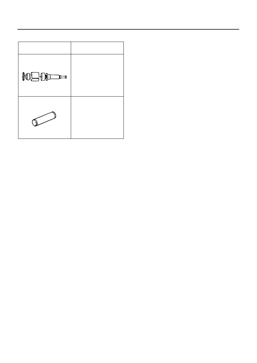
Special Tools

Illustration

Tool No.

Tool Name

5-8840-2587-0

Bearing Remover

5-8840-2244-0

Bearing Installer

5884025870

5884022440

Automatic Transmission (Smoother) 7B-121

Control Box

Components


Legend

1. Cover

17. 2-4-6-r Shift Solenoid and O-ring 

2. Lever Bushing 

18. 1-3-5 Shift Solenoid and O-ring 

3. Relay Lever

19. Gear Select Position Sensor and O-ring 

4. Relay Lever Shaft

20. Internal Lever 

5. Breather Pipe, Breather Hose, and Clip

21. Select Lever

6. Spring

22. Spring Pin and Stopper Ring

7. Spring Seat

23. Shift Lever Shaft Oil Seal B

8. Spring

24. Gear Shift Position Sensor and O-ring 

9. Spring Seat

25. Spring Pin and Select Internal Lever 

10. Spring

26. Neutral Switch

11. Shift Lever Shaft Oil Seal A

27. Gearshift Control Box

12. Spring Pin; Shift Lever Shaft 

28. Spring Pin and Joint; Select Solenoid 

13. Shift Lever Shaft

29. Select Solenoid and O-ring 

14. Spring Pin and Joint; 1-3-5 Shift Solenoid

30. Select External Lever Oil Seal 

15. Spring Pin and Joint; 2-4-6-R Shift Solenoid

31. Select External Lever 

16. Plate

N7A1264E

7B-122 Automatic Transmission (Smoother)

Disassembly

1. Remove the neutral switch (1), the breather pipe,

breather hose and clip (2), the gear select position
sensor and O-ring (3), and the gear shift position
sensor (4). 

2. Remove the plate (10).

a. Remove the select solenoid, 2-4-6-R shift

solenoid, and 1-3-5 shift solenoid connectors
from the plate. 

b. Remove the plate from the gearshift control

box.

3. Remove 2-4-6-R shift solenoid (11) and 1-3-5

shift solenoid (12). 

4. Remove the cover (9).
5. Remove the select solenoid (5). 
6. Remove 2-4-6-R shift solenoid, 1-3-5 shift

solenoid, and select solenoid O-rings (6) and joints
(8). 
a. Remove the O-rings from the solenoids.

b. Use a spring pin remover to remove the spring

pins (7), and then remove the joints. 

7. Use a spring pin remover to remove the spring pin

(17), and then remove the select internal lever (16),
and select external lever and washer (13). 

8. Remove the relay lever (15).

• Remove the lever bushing (14) from the relay

lever. 

N7A1265E

N7A1266E

N7A1267E

Automatic Transmission (Smoother) 7B-123

9. Use a spring pin remover to remove the relay lever

shaft. 

10. Use pliers to remove the spring pin; stopper ring

and spring pin; shift lever shaft. 

11. Mark where the shift lever shaft and internal lever

align. 

12. Pull out the shift lever shaft (18), and remove the

stopper ring (25), internal lever (24), spring (23),
spring seat (22), spring (21), spring seat (20), and
spring (19). 

N7A1268E

N7A1269E

N7A1270E

N7A1271E


Content   ..  969  970  971  972   ..