Isuzu N-Series. Manual - part 945


  Index      Isuzu     Isuzu N-Series - service repair manual


Search            


Content   ..  943  944  945  946   ..


Isuzu N-Series. Manual - part 945


7B-16 Automatic Transmission (Smoother)

Gear Select Position Sensor

Removal

1. Connector
2. Remove the gear select position sensor.
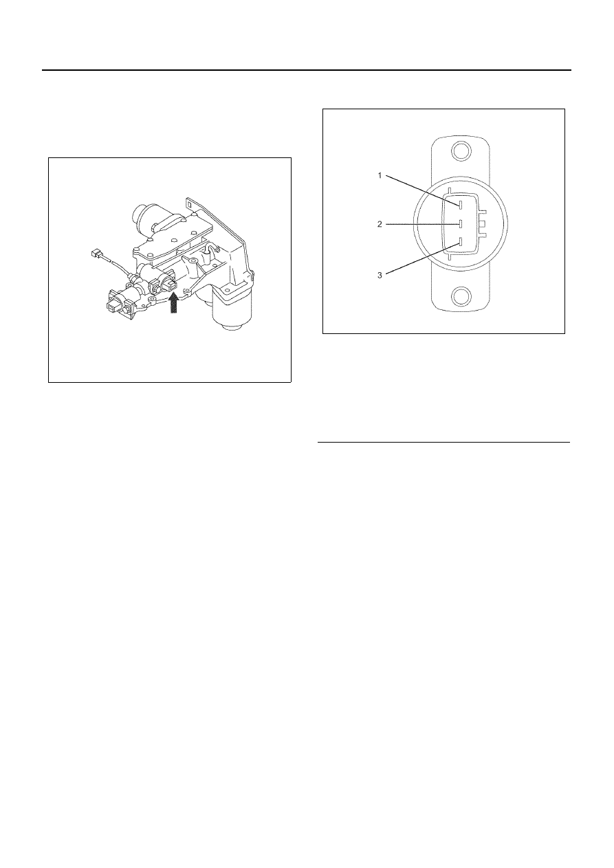
Inspection

Connect the gear select position sensor terminal 3
(SEL.VCC) to 5 V and terminal 1 (SEL.GND) to ground.
Record the voltage between terminals 2 (SEL.SIG) and
1 (SEL.GND) while rotating the sensor arm.
Replace if the voltage does not vary from approximate
0.1 to 4.8 V.


Installation

1. Confirm there is an O-ring on the case side, apply

Besco chassis grease to the sliding portion of the
sensor shaft tip and install. 

2. Install the gear select position sensor.

a. Aligning the angle of the sensor arm tip with the

connector part groove, carefully insert the gear
select position sensor. 

b. Install the gear select position sensor using the

bolt.

Tighten:
9 N

⋅m (0.9 kg⋅m / 6.6 lb⋅ft)

N7A1018E

Legend

1. Gear Select Position Sensor Terminal 1 

(SEL.GND)

2. Gear Select Position Sensor Terminal 2 

(SEL.SIG)

3. Gear Select Position Sensor Terminal 3 

(SEL.VCC)

N7A1016E

Automatic Transmission (Smoother) 7B-17

N7A1018E

7B-18 Automatic Transmission (Smoother)

Neutral Switch

Removal

1. Connector
2. Neutral switch

Inspection

• Replace if the harness, the connector or the seal is

damaged.

• Normal operation is indicated if there is continuity

between switch terminals when measured as-is,
and if there is no continuity between the terminals
when the ball is pressed. 

• The switch operation stroke is 0.93 mm. 

Installation

1. Neutral switch

• Apply Loctite 242 (or equivalent) to the threads

of the switch and install.

Tighten:
34 N

⋅m (3.5 kg⋅m / 25.1 lb⋅ft)

2. Connector

N7A1021E

N7A1022E

Automatic Transmission (Smoother) 7B-19

Reverse Switch

Removal

1. Connector
2. Reverse switch

Inspection

• Replace if the harness, the connector or the seal is

damaged.

• Normal operation is indicated if there is continuity

between switch terminals when measured as-is,
and if there is no continuity between the terminals
when the ball is pressed. 

• The switch operation stroke is 0.93mm. 

Installation

1. Reverse switch

• Apply Loctite 242 (or equivalent) to the threads

of the switch and install.

Tighten:
39 N

⋅m (4.0 kg⋅m / 28.8 lb⋅ft)

2. Connector

N7A1023E

N7A1022E


Content   ..  943  944  945  946   ..