Isuzu N-Series. Manual - part 944


  Index      Isuzu     Isuzu N-Series - service repair manual


Search            


Content   ..  942  943  944  945   ..


Isuzu N-Series. Manual - part 944


7B-12 Automatic Transmission (Smoother)
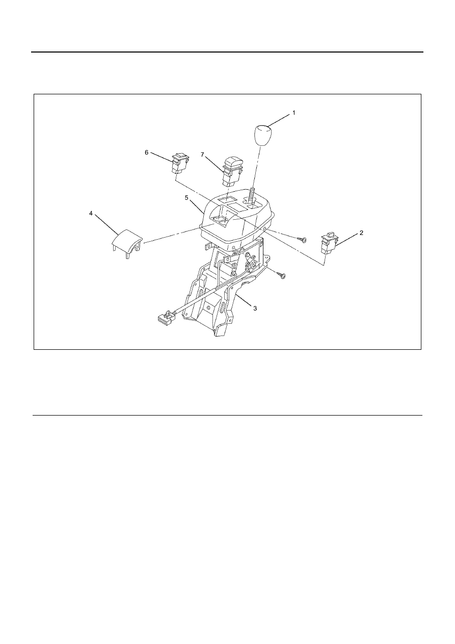
Selector Lever

Components


Disassembly

1. Remove the selector lever knob. 
2. Remove the selector lever cover. 

• Remove the fours screws that secure the

selector lever cover in place, and remove the
selector lever cover. 

3. Remove the switch cover from the selector lever

cover. 

4. Remove the emergency shift switch, emergency

switch, and mode switch from the selector lever
cover. 

Assembly

1. Install the mode switch, emergency switch, and

emergency shift switch on the selector lever cover. 

2. Install the switch cover on the selector lever cover. 

3. Install the selector lever cover.

• Install the selector lever cover and secure it

with the four selector lever cover screws. 

4. Install the selector lever knob.

Legend

1. Selector Lever Knob

5. Selector Lever Cover

2. Emergency Shift Switch

6. Emergency Switch

3. Selector Lever Assembly

7. Mode Switch (Economy, 1st Gear Start) 

4. Switch Cover

N7A1012E

Automatic Transmission (Smoother) 7B-13

Vehicle Speed Sensor

Removal

1. Remove the clip (1) and remove the protector (2). 
2. Disconnect the wire connector.

3. Remove the fixing screw and then remove the

vehicle speed sensor (3). 


Installation

1. Use the fixing screw to install the vehicle speed

sensor. 

Fixing screw

Tighten:
20 N

⋅m (2.0 kg⋅m / 14.8 lb⋅ft)

Bushing — Vehicle speed sensor

Tighten:
25 N

⋅m (2.5 kg⋅m / 18.4 lb⋅ft)

2. Connect the wire connector.
3. Secure the protector with the clip. 

Legend

1. Plug Sensor
2. Vehicle Speed Sensor
3. Plate
4. Bush
5. O-ring
6. Driven Gear

N7A1013E

N7A1014E

7B-14 Automatic Transmission (Smoother)

Gear Shift Position Sensor

Removal

1. Connector
2. Remove the gear shift position sensor.

Inspection

Connect the gear shift position sensor terminal 3
(SFT.VCC) to 5 V and terminal 1 (SFT.GND) to ground.
Record the voltage between terminals 2 (SFT.SIG) and
1 (SFT.GND) while rotating the sensor arm.
Replace if the voltage does not vary from approximately
0.1 to 4.8 V.


Installation

1. Apply Besco chassis grease to the sensor shaft tip

and the sliding portion of the gearshift control box
shaft tip groove, and install. 

2. Install the gear shift position sensor.

a. Aligning the angle of the sensor arm tip with

connector part groove, carefully insert the gear
shift position sensor. 

b. Install the gear shift position sensor using the

bolt.

Tighten:
9 N

⋅m (0.9 kg⋅m / 6.6 lb⋅ft)

N7A1015E

Legend

1. Gear Shift Position Sensor Terminal 1 

(SFT.GND)

2. Gear Shift Position Sensor Terminal 2 

(SFT.SIG)

3. Gear Shift Position Sensor Terminal 3 

(SFT.VCC)

N7A1016E

Automatic Transmission (Smoother) 7B-15

N7A1015E


Content   ..  942  943  944  945   ..