Isuzu N-Series. Manual - part 873


  Index      Isuzu     Isuzu N-Series - service repair manual


Search            


Content   ..  871  872  873  874   ..


Isuzu N-Series. Manual - part 873


7B1-16 MANUAL TRANSMISSION (MZZ)

17. Use the remover (5-8840-0027-0) and the sliding

hammer (5-8840-0084-0) to remove the neutral
bearing (main end) from the rear cover.

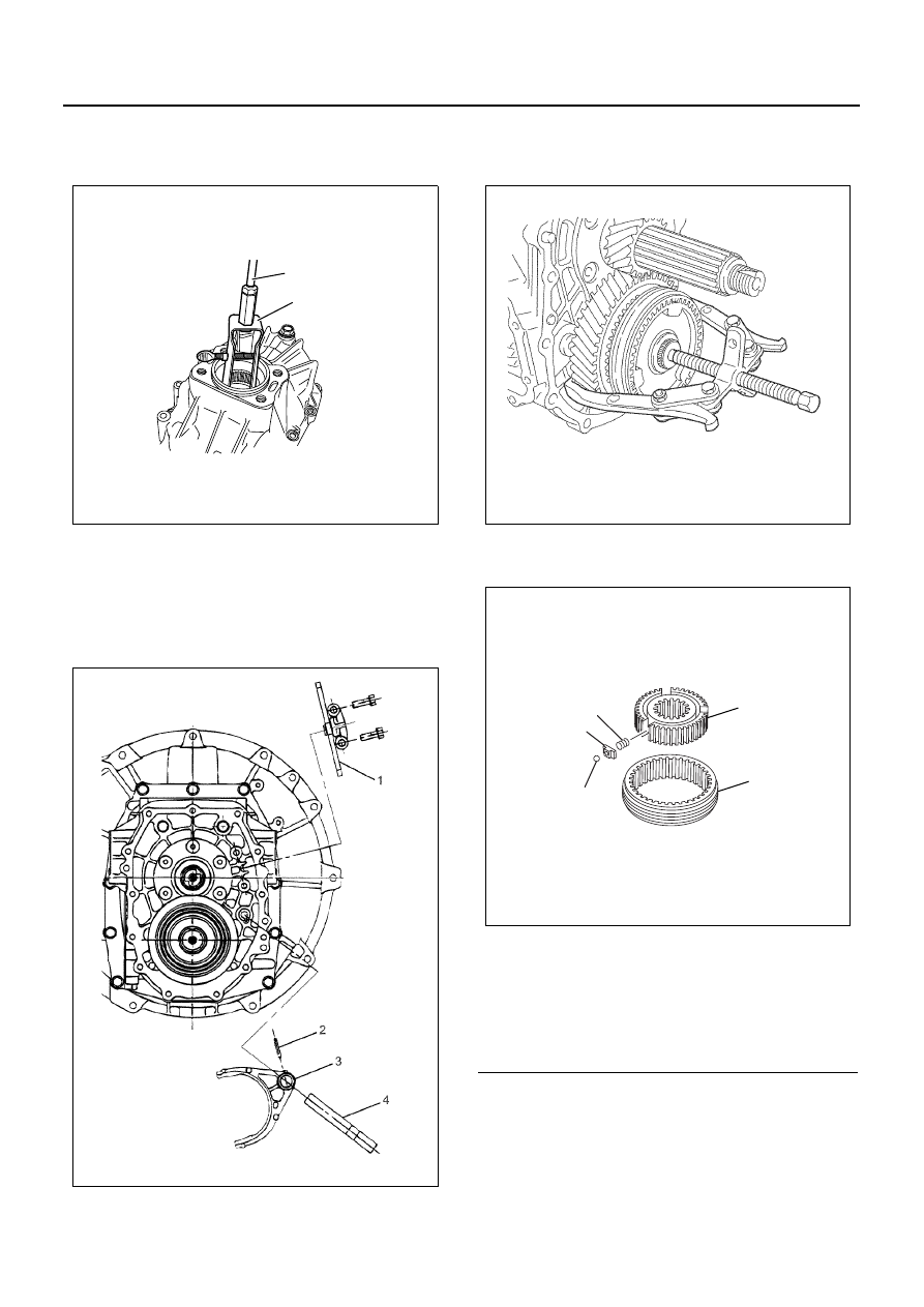
18. Remove the relay lever 6th gear (1).
19. Use a spring remover to force out the spring pins

(2) from the 6th gear shift arm (3) and the 6th gear
shift rod (4).

20. Remove the 6th gear shift arm and the 6th gear

shift rod.

21. Use a pair of snap ring pliers to remove the snap

ring from the 6th gear clutch hub.

22. Use a puller to remove the 6th gear clutch hub as-

sembly, the sleeve, the block ring, the gear, and
the needle bearing from the counter shaft.

23. Disassemble the 6th gear clutch hub assembly and

the sleeve.

24. Remove the speedometer gear.
25. Remove the retainer from the transmission case.
26. Pull out the reverse idle shaft.
27. Remove the reverse idle gear together with the

needle bearing.

5-8840-0084-0

5-8840-0027-0

N7A0348E

N7A1140E

Legend

1. Clutch hub
2. Sleeve
3. Ball
4. Block
5. Spring

N7A1141E

1

5

4

3

2

N7A0372E

MANUAL TRANSMISSION (MZZ) 7B1-17

28. Remove the snap ring (rear outer) from the main

shaft rear bearing.

29. Remove the shim from the counter shaft rear bear-

ing.

30. Remove the snap rings (4th / 5th and 6th shift

rods).

31. Remove the transmission case from the clutch

housing.

32. Remove the bearing rear outer race from the trans-

mission case.

33. Use a spring pin remover to remove the spring pins

from the 4th / 5th shift rod, the 1st / reverse shift
block, the 6th shift block, and 4th / 5th shift arm.

34. Remove the 4th / 5th shift rod, the 1st / reverse shift

block, the 6th shift block, and 4th / 5th shift arm.

Caution:
To avoid damaging other parts, place a round shaft at
the opposite end of the shift rod when removing the
spring pins.

35. Remove the 1st / reverse and the 2nd / 3rd shift

rod, the 1st / reverse shift arm, the 2nd / 3rd shift
arm, the 1st / reverse, and the 6th shift block.

Caution:
To avoid damaging other parts, place a round shaft at
the opposite end of the shift rod when removing the
spring pins.

N7A1090E

N7A0353E

N7A0316E

N7A1147E

7B1-18 MANUAL TRANSMISSION (MZZ)

36. Use the remover (5-8840-2755-0) to remove the

bush from the 4th / 5th shift arm.

37. Use the remover (5-8840-2755-0) to remove the

bush from the 1st / reverse shift arm.

38. Use the remover (5-8840-2755-0) to remove the

bush from the 2nd / 3rd shift arm. from the 1st / re-
verse shift arm.

Caution:
To avoid damaging other parts, place a round shaft at
the opposite end of the shift arm (same length as the re-
mover) when removing the bushes.

39. Remove the magnet from the clutch housing.
40. Remove the main shaft assembly, upper gear shaft

assembly, and the countershaft assembly.
a. Tightly wrap belts such as lashing belts around

the main shaft assembly, upper gear shaft as-
sembly, and the countershaft assembly in two
or more places to prevent the assemblies from
separating.

b. Secure the bearing remover to the main shaft

with the lock nut, then raise it with a hoisting ca-
ble. Spread the outer snap ring of the upper
gear shaft bearing, which is attached to the
clutch housing, and simultaneously remove up-
per gear shaft assembly, main shaft assembly,
and countershaft assembly from the clutch
housing.

N7A1148E

N7A1094E

N7A1095E

N7A0356E

MANUAL TRANSMISSION (MZZ) 7B1-19

41. Inspect the clutch housing bush for wear and dam-

age. If wear or damage is present, the bush must
be replaced. Remove the old bush from the clutch
housing with a pair of pliers.

42. Inspect the front oil seal for wear and damage. If

wear or damage is present, the seal must be re-
placed. Remove the old seal from the clutch hous-
ing with an ordinary screwdriver.

43. Inspect the other parts for wear and damage. If

wear or damage is present, make the necessary
repairs or replace the part(s).

44. Inspect the shift rod and the shift arm (shift mech-

anism) for bending, wear, and other damage. If mi-
nor wear or damage is present, make the
necessary repairs. If major wear or damage is
present, the part(s) must be replaced.

45. Use a micrometer to measure the shift arm end

thickness. If the thickness exceeds the specified
limit, the shift arm must be replaced.

46. Inspect the speedometer driven gear and the driv-

en gear bush for wear and other damage. Replace
the driven gear and bush if significant wear is
present.

Reassembly

1. Inspect the oil seal for wear and damage. If dam-

age or wear is present, the seal must be replaced.

2. Apply engine oil (5W-30) to the outside circumfer-

ence of the oil seal.

3. Apply multi-purpose type grease to the lipped por-

tion of the oil seal.

N7A1097E

N7A1098E

Shift arm end thickness

mm (in)

Gear

Standard

Limit

1st / reverse

3rd / 2nd

5th / 4th

9.60 — 9.85

(0.378 — 0.388)

9.00

(0.354)

6th

9.60 — 9.85

(0.378 — 0.388)

9.30

(0.366)

N7A1100E

N7A1101E


Content   ..  871  872  873  874   ..