Isuzu N-Series. Manual - part 871


  Index      Isuzu     Isuzu N-Series - service repair manual


Search            


Content   ..  869  870  871  872   ..


Isuzu N-Series. Manual - part 871


7B1-8 MANUAL TRANSMISSION (MZZ)

Inspect

Check the cables for any deformation, damage or rust,
and also check the sliding portion for any abnormal con-
dition.
When there is any abnormal condition found, replace it
with new one.

Install or Connect

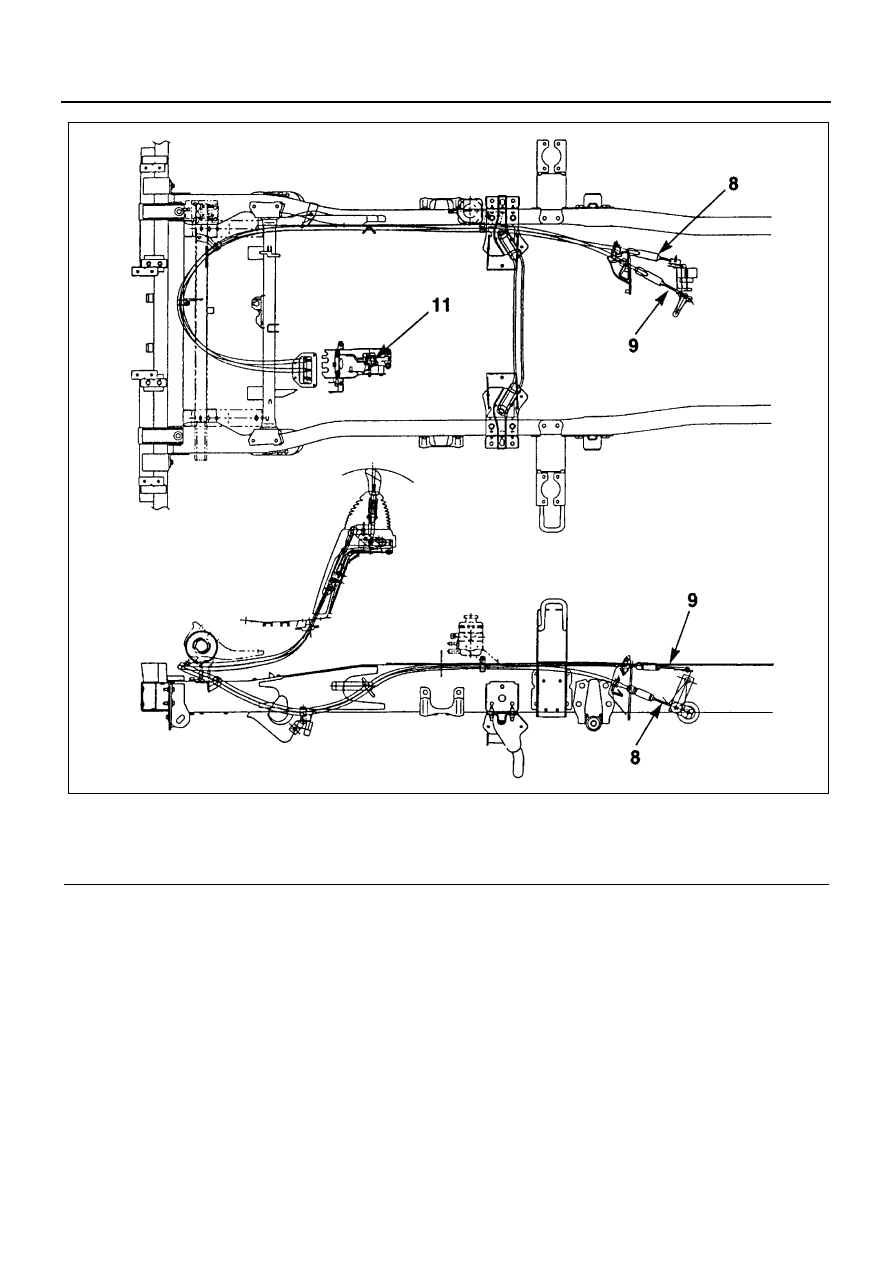
1. Shift cable (8) and select cable(9).

• Install temporarily the shift cable and select cable.

Important:

• Never bend the cables to radius less than 450 mm

(18 in) unless it is necessary to do so for wiring pur-
poses. And never bend the cables to radius less
than 180 mm (7 in) even during wiring.

• Install the cables carefully without unnecessary

twisting the cable boots.

• Fasten the cables with C-clips to the brackets on

the transmission side.

• Fasten the cables with C-clips to the gearshift lever

bracket.

• Fasten the cables with clips to the frames and

brackets.

• Connect the cables to the transmission.

• Install the grommet (19), grommet seal (18) and

grommet retainer (17).

Legend

8. Shift cable

11. Gearshift lever

9. Select cable

N7A0523E

MANUAL TRANSMISSION (MZZ) 7B1-9

Adjust:

• When connecting the shift cable (8) and the select

cable (9) to the gearshift lever, adjust the cables.
Refer to GEARSHIFT CABLE given previously in
this section.

2. Cover assembly (5).
3. Gearshift lever knob (4).

• Connect the battery negative cable and remove the

wheel blocks.

Vehicle Speed Sensor

Removal

1. Remove the clips (1) and the protector (2).
2. Remove the wiring connectors.

3. Loosen the fixing screw and remove the vehicle

speed sensor (2).

Installation

1. Install the vehicle speed sensor and secure it with

the fixing screw.

• Align the gear tooth marked 17 of the speedome-

ter's driven gear (17 teeth) with the opening in the
plate.

2. Tighten the fixing screw to the specified torque.

Tighten:
Screw to 20 N

⋅m (2.0 kg⋅m / 15 lb⋅ft)

3. Install the sensor insert and the vehicle speed sen-

sor. Tighten the vehicle speed sensor to the spec-
ified torque.

Tighten:
Vehicle speed sensor to 25 N

⋅m (2.5 kg⋅m / 18 lb⋅ft)

4. Connect the wiring connectors.
5. Install the protector and secure it with the clips.

Reverse, Neutral and Selector Switches

Removal

1. Remove the wiring connectors.
2. Remove the reverse switch (2). The switch has a

black connector.

3. Remove the neutral switch (1). The switch has a

black connector.

1

2

N7A0289E

N7A1014E

Legend

1. Sensor insert
2. Vehicle speed sensor
3. Plate
4. Bush
5. O-ring
6. Driven gear

17

11

10

N7A0524E

7B1-10 MANUAL TRANSMISSION (MZZ)

Inspection

1. Check for continuity between the switch terminals

when the ball is pressed. If there is no continuity,
the switch is bad.

2. Measure the switch travel.

Switch travel: 0.93 mm (0.03 in)

Installation

1. Apply liquid gasket (Three Bond 1141) to the

threaded portion of the neutral switch.

2. Install the neutral switch. Tighten the switch to the

specified torque.

Tighten:
Switch to 34 N

⋅m (3.5 kg⋅m / 25 lb⋅ft)

3. Apply liquid gasket (Three Bond 1141) to the

threaded portion of the reverse switch.

4. Install the reverse switch. Tighten the switch to the

specified torque.

Tighten:
Switch to 39 N

⋅m (4 kg⋅m / 29 lb⋅ft)

1

2

N7A0291E

0.93 mm

(0.03 in)

N7A0292E

MANUAL TRANSMISSION (MZZ) 7B1-11

Rear Oil Seal

Parts

Removal

1. Remove the rear propeller shaft assembly.

• Refer to PROPELLER SHAFT.

2. Remove the parking brake cable.

• Refer to PARKING BRAKES.

3. Remove the parking brake drum.

• Refer to PARKING BRAKES.

4. Use the special tool (9-8529-2101-0) to break the

coupler driver lock nut caulking (2 locations) and
remove the nut.

5. Remove the coupling driver together with the O-

ring.

6. Remove the parking brake assembly.

• Refer to PARKING BRAKES.

7. Use an ordinary screwdriver to remove the rear oil

seal.

Installation

1. Apply engine oil (5W-30) to the new oil seal outer

circumference.

2. Apply multi-purpose type grease to the lipped por-

tion of the oil seal.

3. Use the installer (5-8840-2751-0) to press the oil

seal into the rear cover.

Caution:
The lipped portion of the oil seal is easily broken. Exer-
cise care during the installation procedure.

4. Install the parking brake assembly.

• Refer to PARKING BRAKES.

5. Apply engine oil (5W-30) to the new O-ring.
6. Install the coupling driver together with the O-ring.
7. Apply engine oil (5W-30) to the seating surface of

the new lock nut.

8. Use the special tool (9-8529-2101-0) to tighten the

lock nut to the specified torque.

Tighten:
Lock nut to 382 N

⋅m (39 kg⋅m / 282 lb⋅ft)

Legend

1. Oil seal

4. Coupling driver

2. Parking brake cable

5. Parking brake drum

3. Parking brake assembly

6. Rear propeller shaft assembly

N7A0525E

5-8840-2751-0

N7A0567E


Content   ..  869  870  871  872   ..