Isuzu N-Series. Manual - part 828
7C-14 CLUTCH
UNIT REPAIR
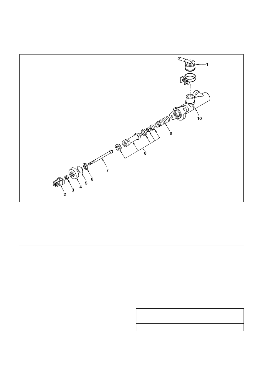
Master Cylinder
Disassembly
1. Pipe Joint
2. Clevis Yoke
3. Lock Nut
4. Dust Cover
5. Snap Ring
• Press down the piston with your finger to pre-
vent it from jumping out.
6. Stopper
7. Push Rod
8. Piston Assembly
9. Return Spring
10. Cylinder Body
Inspection and Repair
Make the necessary adjustments, repairs, and parts re-
placements if excessive wear or damage is discovered
during inspection.
Cylinder Body
• Wash clean the cylinder body in brake fluid.
• Check the fluid return port for restrictions and
clean it if necessary.
• Measure the cylinder bore diameter.
Legend
1. Pipe joint
6. Stopper
2. Clevis yoke
7. Push rod
3. Lock nut
8. Piston assembly
4. Dust cover
9. Return spring
5. Snap ring
10. Cylinder body
N7A0231E
Master Cylinder Bore Diameter
mm (in)
Standard
φ19.050 — 19.102 (0.7500 — 0.7520)