Isuzu N-Series. Manual - part 826


  Index      Isuzu     Isuzu N-Series - service repair manual


Search            


Content   ..  824  825  826  827   ..


Isuzu N-Series. Manual - part 826


7C-6 CLUTCH

Clutch Cover

• Visually inspect the entire clutch cover for ex-

cessive wear, cracking, and other damage.
The pressure plate assembly must be replaced
if any of these conditions are present.
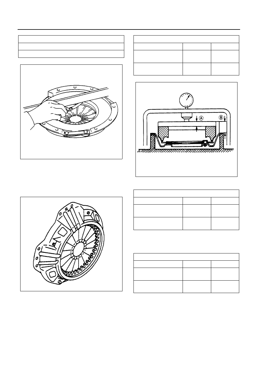
Clutch Set Force

1) Invert the pressure plate assembly.
2) Place a metal sheet with thickness “A” on the

pressure plate.

3) Compress the pressure plate assembly until

the distance “B” becomes specified.

4) Note the pressure plate gauge reading.

Diaphragm Spring Finger Height

1) Place distance pieces beneath the pressure

plate and clutch cover.

2) Fully compress the pressure plate assembly.

There are two ways to do this.

a. Use a bench press to press down on the pres-

sure plate assembly from the top.

b. Tighten the pressure plate assembly fixing

bolts.

3) Measure the spring finger height from base to

spring tip.

Pressure Plate Warpage

mm (in)

Limit

0.3 (0.01)

N7A0214E

N7A0215E

Thickness and Distance

mm (in)

A

B

NKR55
Clutch Size 

φ 240

7.4 (0.29)

18 (0.71)

NHR55/NKR55/NHR69
Clutch Size 

φ 250

8.0 (0.31)

18 (0.71)

Clutch Set Force

N (kg/lb)

Standard

Limit

NKR55
Clutch Size 

φ 240

4,116

(420/926)

3,785

(386/851)

NHR55/NKR55/NHR69
Clutch Size 

φ 250

6,276

(640/1,411)

5,776

(589/1,299)

Distance Piece

mm (in)

A

B

NKR55
Clutch Size 

φ 240

7.4 (0.29)

18 (0.71)

NHR55/NKR55/NHR69
Clutch Size 

φ 250

8.0 (0.31)

18 (0.71)

N7A0571E

CLUTCH 7C-7

Driven Plate Assembly

• Visually inspect the torsion spring for loose-

ness, breakage, and weakening.
If any of these conditions are discovered, the
driven plate assembly must be replaced.

• Visually inspect the facing surfaces for cracking

and excessive scorching.
Visually inspect the facing surfaces for the
presence of oil or grease.
If any of these conditions are discovered, the
facing must be cleaned or the driven plate as-
sembly replaced.

• Check that the driven plate moves smoothly on

the transmission top gear shaft spline.
Minor ridges on the top gear shaft spline may
be removed with an oil stone or pencil grinder.

Driven Plate Warpage

• Insert the pilot aligner into the driven plate

spline hub.
The pilot aligner must be held perfectly horizon-
tal.
Pilot Aligner: 5-8525-3001-0

• Set a dial indicator to the driven plate outside

circumference.

• Slowly turn the driven plate.

Read the dial indicator as you turn the driven
plate.
If the measured value exceeds the specified
limit, the driven plate assembly must be re-
placed.

Spring Finger Height (H)

mm (in)

Standard

NKR55
Clutch Size 

φ 240

40.7 — 42.7

(1.60 — 1.68)

NHR55/NKR55/NHR69
Clutch Size 

φ 250

39.0 — 41.0

(1.54 — 1.61)

N7A0217E

Driven Plate Warpage

mm (in)

Standard

Limit

Less than 0.7 (0.03)

1.0 (0.04)

N7A0218E

N7A0219E

7C-8 CLUTCH

Driven Plate Splined Hub Spline Wear

• Clean the driven plate splined hub.
• Install the driven plate to the transmission top

gear shaft spline.

• Set a surface gauge to the driven plate outside

circumference.

• Slowly turn the driven plate. Measure the spline

rotation play as you turn the driven plate.
If the measured value exceeds the specified
limit, the driven plate assembly must be re-
placed.

Driven Plate Rivet Head Depression

• Use the depth gauge or a straight edge with

steel rule to measure the rivet head depression
(1) from the facing surface (2).
Be sure to measure the rivet head depression
(1) on both sides of the driven plate (2).
If the measured value is less than the specified
limit, the driven plate must be replaced.

Shift Fork and Support Bolt

• Visually inspect the surfaces of the shift fork

making contact with the shift block (release
bearing) and support bolt.

• Correct a slight stepped wear or surface rough-

ness with an oil stone or pencil grinder, or re-
place the shift fork and/or support bolt if
unrecoverable damage is found.

• Apply multi-purpose with MOS

2

 type grease.

Release Bearing Assembly

• Visually inspect the release bearing assembly

for breakage and weakening.

• If any of these conditions are discovered, re-

lease bearing assembly must be replaced.

Caution:
The release bearing is permanently packed with lubri-
cant and should not be soaked in cleaning solvent, as
this will dissolve the lubricant.

Driven Plate Splined Hub 
Spline Wear

mm (in)

Standard

Limit

Less then 0.5 (0.02)

1.0 (0.04)

Rivet Head Depression

mm (in)

Standard

Limit

NKR55
Clutch Size 

φ 240

1.1 — 1.7

(0.04 — 0.07)

0.2 (0.01)

NHR55/NKR55/NHR69
Clutch Size 

φ 250

1.65 — 2.25

(0.06 — 0.09)

0.2 (0.01)

N7A0220E

N7A0221E

N7A0222E

CLUTCH 7C-9

Notice:
Do not disassemble the shift block assembly if no fault
is apparent.

• Use the bearing remover and bench press to

remove the release bearing.
Bearing Remover: 5-8840-0013-0

• Install the parts as shown after applying multi-

purpose with MOS

2

 type grease.

Use a bench press.

Support Spring

• Visually inspect the support spring for break-

age and weakening.

• If any of these condition are discovered, parts

must be replaced.

Installation

1. Pilot Bearing

• Use the pilot bearing installer to install the

clutch pilot bearing.
Pilot Bearing Installer: 5-8522-0024-0

2. Shift Fork

• Apply multi-purpose with MOS

2

 type grease to

the contact surfaces with the shift block and
support bolt head.

N7A0223E

N7A0224E

N7A0225E

N7A0227E


Content   ..  824  825  826  827   ..