Isuzu N-Series. Manual - part 823
7B-62 MANUAL TRANSMISSION (MSB)
Unit Repair
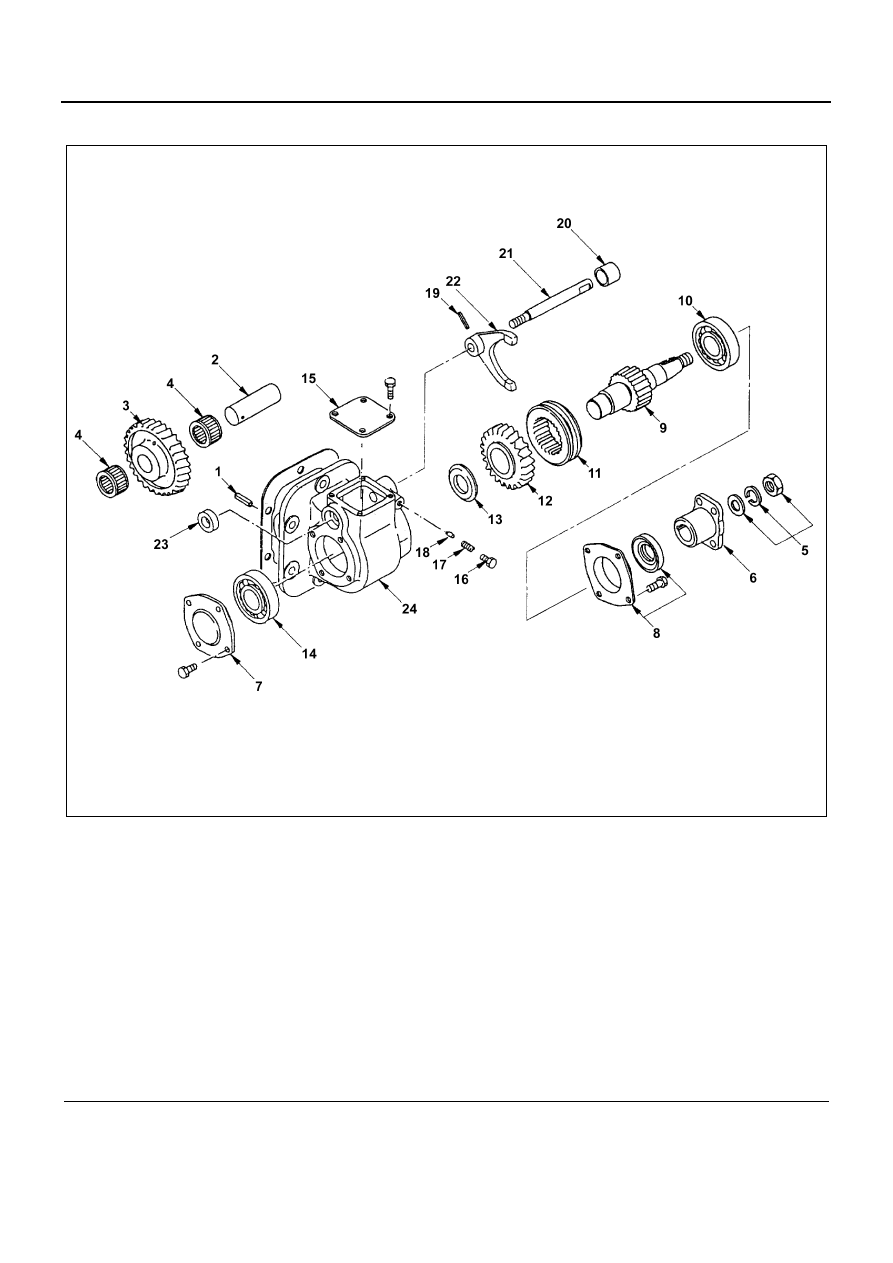
Legend
1. Spring pin
13. Thrust collar
2. Idle gear shaft
14. Front bearing
3. Idle gear
15. Upper cover
4. Needle bearing
16. Plug
5. Lock nut and washer
17. Detent spring
6. Coupling driver
18. Detent pin
7. Front cover
19. Spring pin
8. Rear cover with oil seal
20. Shift rod plug
9. Output shaft
21. Shift rod
10. Rear bearing
22. Shift arm
11. Sleeve
23. Shift rod oil seal
12. Output gear with bushing
24. Gear case
N7A0185E