Isuzu N-Series. Manual - part 819


  Index      Isuzu     Isuzu N-Series - service repair manual


Search            


Content   ..  817  818  819  820   ..


Isuzu N-Series. Manual - part 819


7B-46 MANUAL TRANSMISSION (MSB)

• Wears or damages found on the clutch hub, the

sliding sections of the sleeve, the spline sec-
tions and insert grooves.

Block Ring and Dog Gear Teeth 
Clearance

mm (in)

Gear

Standard

Limit

3rd/4th

1.0 (0.04)

0.5 (0.02)

1st/2nd

1.5 (0.06)

0.5 (0.02)

5th

1.5 (0.06)

0.5 (0.02)

N7A1203E

N7A1204E

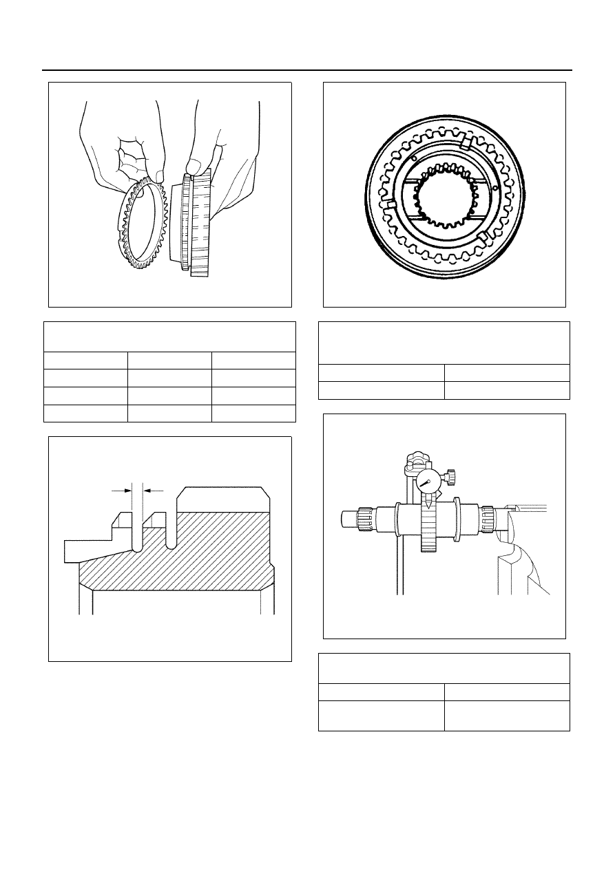
Clutch Hub Spline Play 
(At clutch hub outer cir-
cumference)

mm (in)

Standard

Limit

0 — 0.05 (0 — 0.002)

0.3 (0.01)

Block Ring Groove and 
Insert Clearance

mm (in)

Standard

Limit

3.59 — 3.91 (0.141 — 

0.154)

4.1 (0.16)

N7A0147E

N7A1206E

MANUAL TRANSMISSION (MSB) 7B-47

Shift Mechanism
Inspect all disassembled parts for wear, damage or oth-
er abnormal conditions.

• Check the shift rod for wear, bent and damage.

• Check the shift arm and shift block groove for

wear or deformation.

• Check the detent spring for weakening and de-

formation.

Clutch Hub Groove and 
Insert Clearance

mm (in)

Standard

Limit

0.09 — 0.31 (0.004 — 

0.012)

0.4 (0.02)

N7A0149E

N7A0150E

Shift Arm Thickness

mm (in)

Standard

Limit

10.0 (0.39)

9.0 (0.35)

Free Length of Detent 
Spring

mm (in)

Standard

Limit

31.6 (1.24)

30.1 (1.19)

N7A0151E

N7A0152E

7B-48 MANUAL TRANSMISSION (MSB)

• The wear of the select lever, and the backlash

and awkward operation of the control box.

Reassembly

Notice:
Clean each part thoroughly.
When assembling parts, apply clean engine oil (SAE
5W-30) to their sliding and mating sections.
Counter Shaft Assembly

1. Spring

• Attach a backing plate to the vise, secure the

counter shaft rear end, and install the springs.

• The spring should be installed to the left of the

inside counter drive gear pin.

Notice:
When replacing the pin with a new one, hammer it in un-
til its height becomes 3 mm (0.12 in) from the gear end
face.

2. Anti-lash Plate

• Assemble the anti-lash plate to the drive gear

so that the drive gear hole (

φ7.7 mm/0.3 in)

comes roughly in line with the hole (

φ7.7 mm/

0.3 in) of the anti-lash plate.

N7A0153E

N7A0154E

N7A0156E

N7A0157E

MANUAL TRANSMISSION (MSB) 7B-49

• With the guide pin aligned with the drive gear

hole (

φ7.7 mm/0.3 in), set the installer to the

guide pin.
Anti-lash Plate Installer: 5-8840-2044-0

• Turn the installer clockwise. When the drive

gear pin comes to the position where it can be
seen fully, put the installer into the drive gear
side to fix the anti-lash plate to the drive gear.

3. Conical Washer

• Install the conical washer above the anti-lash

plate with the convex side (front side) up.

4. Snap Ring

• Use a new snap ring to fix the conical washer.

Notice:
Avoid the reuse of snap ring.
Check visually the anti-lash plate for a warp or curve af-
ter assembly.

Main Shaft Assembly

5. Needle Bearing

• Attach a backing plate to the vise, secure the

main shaft at the spline end.

N7A0158E

N7A0159E

N7A0160E

N7A0161E


Content   ..  817  818  819  820   ..