Isuzu N-Series. Manual - part 816


  Index      Isuzu     Isuzu N-Series - service repair manual


Search            


Content   ..  814  815  816  817   ..


Isuzu N-Series. Manual - part 816


7B-34 MANUAL TRANSMISSION (MSB)

Tighten:
Parking brake nut M12 to 113 N

⋅m (11.5 kg⋅m / 83 lb⋅ft)
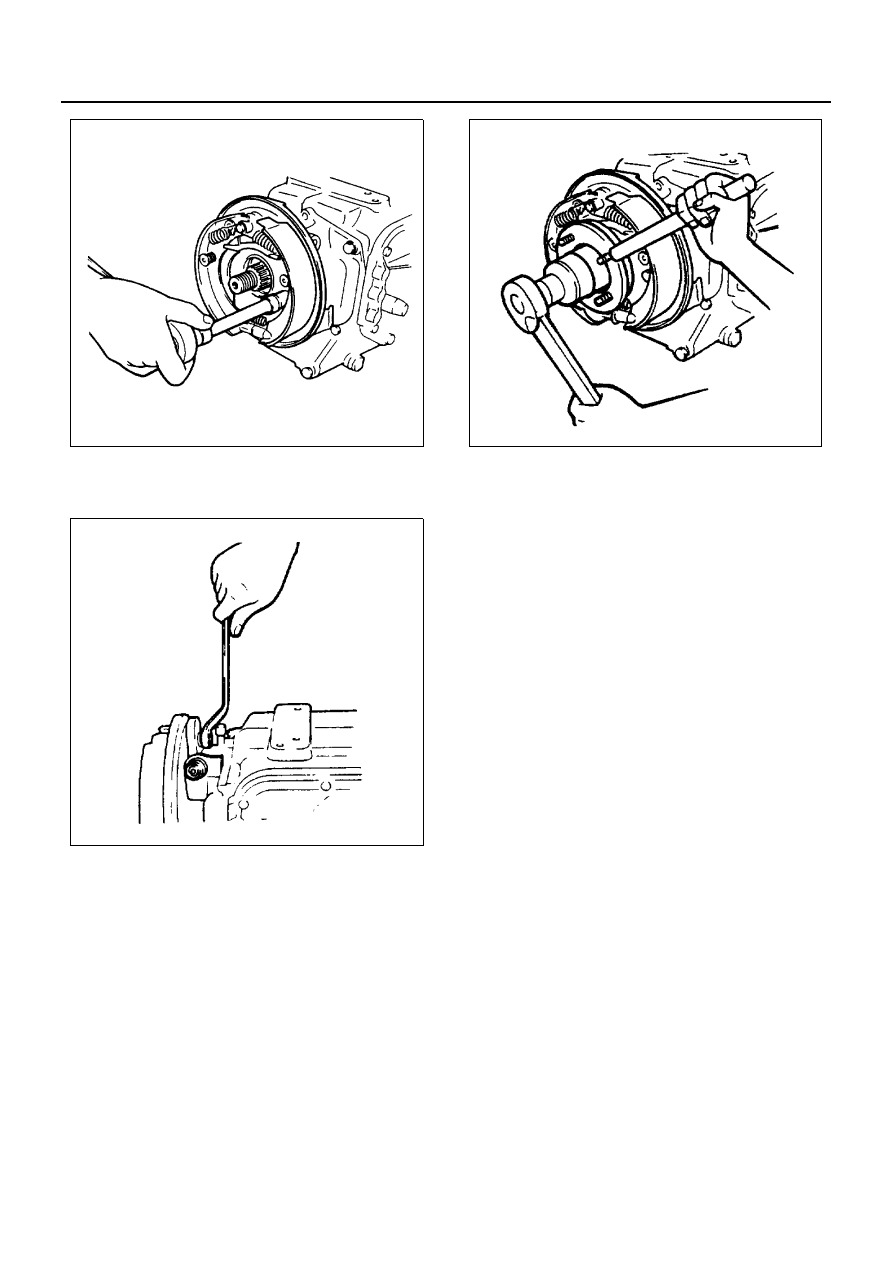
33. Coupling Driver
34. Lock Nut

• Install the O-ring and conical washer. The con-

ical washer is to be set up with its identification
groove to the nut side.

• Apply the engine oil to the setting face of the

new lock nut and tighten it up to the specified
torque.

Caution:
Do not reuse the lock nut.

Handle: 5-8840-2043-0

Tighten:
Lock nut to 226 N

⋅m (23.0 kg⋅m / 166 lb⋅ft)

• Align the lock nut with the V-shaped groove at

the tip of the main shaft, and caulk the nut lip
portion by using a chisel. (Round edge approx-
imately 1 mm (0.04 in) 

× 60°).

• As shown in the illustration, be sure to caulk the

nut lip so that the clearance between the V-
shaped groove portion at the tip of the main
shaft and the caulked up lip (A) is less than 1.5
mm (0.06 in), and the caulking length (B) is 5
mm (0.2 in) or more.

Caution:
Be sure to confirm that there is no crack at the caulked
portion of the lock nut after caulking.

N7A0069E

N7A0129E

N7A0130E

MANUAL TRANSMISSION (MSB) 7B-35

35. Parking Brake Drum

• Adjust the parking brake after installation.

1) Rotate the brake drum to align the adjust hole

with the adjuster.

2) Move the camshaft lever from side to side sev-

eral times to center the brake shoes.

3) Insert a screwdriver into the hole and rotate the

adjuster by pushing it upward until the shoes
drag on the drum.

4) Back off the adjuster 30 notches.

• Install the adjust hole cover.

Tighten:
Adjust hole cover bolt to 8 N

⋅m (0.8 kg⋅m / 69 lb⋅in)

36. Detent Ball
37. Detent Spring
38. Control Box Assembly

• Apply small amount of multi-purpose grease to

the detent balls.

• Install the 3 detent balls and the 3 detent

springs to the transmission case.

• Install the control box assembly with new gas-

ket.

Tighten:
Control box to transmission case bolts to 20 N

⋅m (2.0

kg

⋅m / 14 lb⋅ft)

Notice:
Operating the shift lever and the select lever, make sure
that they shift to each position smoothly.

39. Shift Fork and Support Bolt

Tighten:
Support bolt to 52 N

⋅m (5.3 kg⋅m / 38 lb⋅ft)

N7A0050E

N7A0131E

N7A0132E

7B-36 MANUAL TRANSMISSION (MSB)

40. Release Bearing Assembly

41. Mission Mounting Assembly

Tighten:
Mission mounting bolt to 69 N

⋅m (7.0 kg⋅m / 51 lb⋅ft)

N7A0065E

N7A0064E

N7A0063E

MANUAL TRANSMISSION (MSB) 7B-37

Top Gear Shaft Assembly, Main Shaft Assembly and Counter Shaft Assembly

Legend
Top gear shaft assembly

15. Snap ring

1. Snap ring

16. Thrust washer

2. Ball bearing

17. 2nd gear
18. Needle bearing

Main shaft assembly

19. Block ring

3. Thrust washer

20. Snap ring

4. 5th gear

21. 1st/2nd synchronizer assembly

5. Block ring

22. Block ring

6. Snap ring

23. 1st gear

7. 5th/reverse synchronizer assembly

24. Needle bearing

8. Reverse gear
9. Needle bearing

Counter shaft assembly

10. Snap ring

25. Snap ring

11. 3rd/4th synchronizer assembly 

26. Conical washer

12. Block ring

27. Anti-lash plate

13. 3rd gear

28. Spring

14. Needle bearing

N7A0014E


Content   ..  814  815  816  817   ..