Isuzu N-Series. Manual - part 744


  Index      Isuzu     Isuzu N-Series - service repair manual


Search            


Content   ..  742  743  744  745   ..


Isuzu N-Series. Manual - part 744


 Engine Control System (4JH1)    6E-27

Reading Diagnostic Trouble Codes (DTCs) with The
Tech 2
The procedure for reading DTC(s) is used a diagnostic
Tech 2.  To read DTCs, use the Tech 2 “Read DTC Info
As Stored By ECU”.

Clearing Diagnostic Trouble Codes (DTCs) with The
Tech 2 or without Tech 2
Do not clear DTCs unless directed to do so by the
service information provided for each diagnostic
procedure.  To clear DTCs, use the Tech 2 “Clear DTC
Information”.  If there is no Tech 2, history DTCs can
also be cleared after 40 consecutive driving cycles
without a fault.

Tech 2 Scan Tool

Isuzu recommend using Tech 2.  Refer to the Tech 2
Users Guide for proper start up procedures.

Operating Procedure

1. Press Enter at start screen.
2. Select Diagnostic > appropriate vehicle

identification > Powertrain > 4JH1-TC.

3. The following table shows, which functions are

used the available equipment versions.

F0: Diagnostic Trouble Code
The purpose of this mode is to display stored trouble
code in the ECM.  When “Clear DTC Information” is
selected, “Clear DTC Information”, warning screen
appears.  This screen informs you that by cleaning
DTCs “all stored DTC information in the ECM will be
erased”.

Symptom Code
Symptom Code is located under the DTC column.  A
parenthetic alphabet or number means identification of
the malfunction.  Each DTC includes individual
symptoms, such as DTC P0100 has four symptom
codes (7), (9), (B) and (C).  DTC chart is separated
depending on this symptom code.

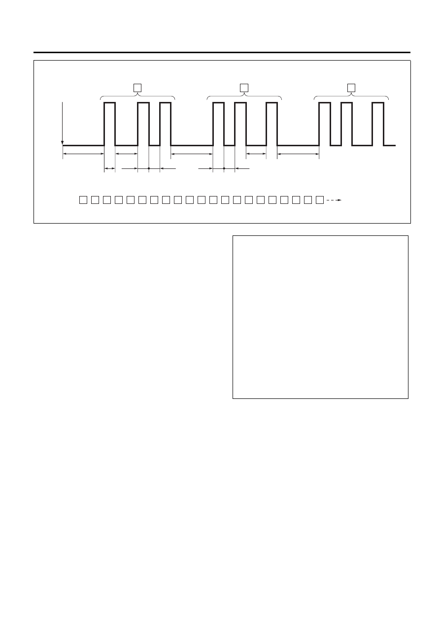
Example: DTC 21,14 and 23 are stored in set order

Diagnosis start

Example: DTC 21 is stored

Continue

21 21 21 14

3.2

3.2

3.2

unit:second

1.2

1.2

0.5

0.5

0.5

0.5

0.5

14 14 23 23 23 12 21 21 21 14 14 14 23 23 23 12

12

12

21

21

ON

OFF

N6A3814E

F0: Diagnostic Trouble Code

F0: Read DTC Info As Stored By ECU

F1: Clear DTC Information

F1: Data Display

F2: Snapshot

F3: Miscellaneous Tests

F0: Lamps

F0: Malfunction Indicator Lamp

F1: Glow Indicator

F1: Relays

F0: Glow Relay

F2: Solenoids

F0: EGR Solenoid Valve

F3: Engine Speed (RPM) Control

F4: Programming

F0: Program VIN

F1: Lock ECU

N6A3815E

6E-28    Engine Control System (4JH1) 

Legend

1. Diagnostic Trouble Code (DTC)
2. Symptom Code


F1: Data Display
The purpose of this mode is to continuously monitor
data parameters.  The current actual values of all
important sensors and signals in the system are display
through this mode.  Refer to the Tech 2 Data List in this
section.

F2: Snapshot
“Snapshot” allow you to focus on making the condition
occur, rather than trying to view all of the data in
anticipation of the fault.  The snapshot will collect
parameter information around a trigger point that you
select.  Refer to the Tech 2 user instructions for more
information.

F3: Miscellaneous Test
The purpose of this mode is to check for correct
operation of electronic system actuators.  Using
miscellaneous test menus can test the state of each
actuator and related sensors.  Especially when DTC
cannot be detected, a faulty circuit can be diagnosed
by testing.  Even DTC has been detected, the circuit
tests using these menus could help discriminate
between a mechanical trouble and an electrical trouble.
Refer to the Tech 2 Output Controls in this section.

F4: Programming
The purpose of this mode is to program the vehicle
identification number (VIN) into the ECM and lock the
programmed VIN.  Refer to Engine Control Module
(ECM) Replacement in this section.

Tech 2 Data List

The Tech 2 Data List contains all engine related
parameters that are available on the Tech 2.  Use the
Tech 2 Data List only after the following is determined:

• The Diagnostic System Check – Engine Controls

is completed.

• No diagnostic trouble codes (DTCs) are present.
• On-board diagnostics are functioning properly.

Tech 2 values from a properly running engine may be
used for comparison with the engine you are
diagnosing.  The Tech 2 Data List represents values
that would be seen on a normal running engine.

Important:
A Tech 2 that displays faulty data should not be used.
The Tech 2 problem should be reported to the
manufacturer.  Use of a faulty Tech 2 can result in
misdiagnosis and unnecessary parts replacement.
Only the parameters listed below are referenced in this
service manual for use in diagnosis.

Read DTC Info As Stored By ECM

P0100

(7)

Present

Mass Air Flow (MAF) Sensor
Circuit 5V Reference  
High Voltage

1

2

N6A3816E

Tech 2 Parameter

Units Displayed

Typical Data Value at 

Engine Idle

Typical Data Value at 2000 

RPM

Operating Conditions: Engine Idling or 2000 RPM / Engine Coolant Temperature is between 75-85

°C (167-185°F) /

Accelerator Pedal is Constant / Park or Neutral / Accessories OFF / Vehicle Located at Sea Level

Ignition Switch

On/Off

On

On

System Voltage

V

11.0 – 15.0

11.0 – 15.0

ECM Main Relay

On/Off

On

On

Engine Speed

RPM

650 – 750

1950 – 2050

Desired Idle Speed

RPM

700

700

Injection Pump Speed

RPM

325 – 375

975 – 1025

Accelerator Pedal Position

%

0.0

19.0 – 23.0

Idle Switch

On/Off

On

Off

Intake Air Temperature

°C/°F

20 – 40

°C / 68 – 104°F

20 – 40

°C / 68 – 104°F

Engine Coolant Temperature

°C/°F

75 – 85

°C / 167 – 185°F

75 – 85

°C / 167 – 185°F

 Engine Control System (4JH1)    6E-29

Tech 2 Data Definitions

A list of each message displayed on the Tech 2 will be
explained in Engine Controls.  This information will
assist in emission or driveability problems.  The
displays can be viewed while the vehicle is being
driven.  Always perform the Diagnosis System Check –
Engine Controls first.  The Diagnostic System Check
will confirm proper system operation.

Ignition Switch
This parameter displays the input status of the ignition
switch to the ECM terminal (pin 39).  The Tech 2 will
display On or Off.  On indicates the ignition switch is
turned ON position.

System Voltage
This parameter displays the system voltage measured
by the ECM terminal (pin 3) at the voltage feed from the
ECM main relay.

ECM Main Relay
This parameter displays the commanded state of the
ECM main relay control circuit (pin 58).  The Tech 2 will
display On or Off.  On indicates the ECM main relay
control circuit is being grounded by the ECM, allowing
the main relay to supply voltage to the other circuits of
the ECM.  Off indicates the main relay is not being
commanded On by the ECM.

Fuel Temperature

°C/°F

20 – 60

°C / 68 – 140°F

20 – 60

°C / 68 – 140°F

Barometric Pressure

hPa

Nearly 1010 hPa at sea 

level

Nearly 1010 hPa at sea 

level

EGR Solenoid Command

%

Nearly 70%

Nearly 30%

Mass Air Flow Sensor

mg/strk

More than 480  mg/strk at 

sea level

More than 1200  mg/strk at 

sea level

Desired Mass Air Flow

mg/strk

More than 480  mg/strk at 

sea level

More than 1200  mg/strk at 

sea level

Actual Injection Quantity

mg/strk

7.0 – 10.0

8.0 – 12.0

Desired Injection Quantity

mg/strk

7.0 – 10.0

8.0 – 12.0

Actual Injection Timing

°CA

3.0 – 5.0

5.0 – 7.0

Desired Injection Timing

°CA

3.0 – 5.0

5.0 – 7.0

Neutral Switch

On/Off

On

On

Brake Pedal 1 Switch

Applied/ 

Released

Released

Released

Brake Pedal 2 Switch

Applied/ 

Released

Released

Released

Clutch Pedal Switch

Applied/ 

Released

Released

Released

Engine Warm Up Switch

On/Off

Off

Off

Exhaust Brake Switch

On/Off

Off

Off

Intake Throttle Solenoid Command

On/Off

Off

Off

Exhaust Brake Solenoid Command

On/Off

Off

Off

ABS Input Signal

On/Off

Off

Off

ABS Output Signal

On/Off

Off

Off

Vehicle Speed

km/h / MPH

0

0

Glow Relay Command

On/Off

Off

Off

Glow Indicator Lamp Command

On/Off

Off

Off

Malfunction Indicator Lamp (MIL) Command

On/Off

Off

Off

A/C Request Signal

On/Off

Off

Off

A/C Relay Command

On/Off

Off

Off

Tech 2 Parameter

Units Displayed

Typical Data Value at 

Engine Idle

Typical Data Value at 2000 

RPM

6E-30    Engine Control System (4JH1) 

Engine Speed
This parameter displays the speed of the crankshaft as
calculated by the ECM based on input from the
crankshaft position (CKP) sensor or camshaft position
(CMP) sensor.  The Tech 2 will display the engine
speed in revolution per minute (RPM).

Desired Idle Speed
This parameter displays the idle speed requested by
the ECM.  The ECM will compensate for various engine
loads based on engine coolant temperature (ECT) and
A/C system status.  If the A/C system is activated, the
ECM sets 50 RPM higher than normal idle speed.

Injection Pump Speed
This parameter displays the speed of the injection
pump as calculated by the fuel injection pump control
unit (PCU) based on the input from the fuel injection
pump camshaft position (CMP) sensor.  The Tech 2 will
display the injection pump speed in revolution per
minute (RPM).

Accelerator Pedal Position
This parameter displays the angle of the accelerator
pedal as calculated by the ECM using the signal from
the accelerator pedal position (APP) sensor.  The
accelerator pedal position indicated angle is a range of
values indicating a low percentage when the
accelerator pedal is not depressed to a high
percentage when the accelerator pedal is fully
depressed.

Idle Switch
This parameter displays the input status of the idle
switch to the ECM terminal (pin 69).  The Tech will
display On or Off.  On indicates the accelerator pedal is
not being pushed down.  Off indicates the accelerator
pedal is being depressed.

Intake Air Temperature
This parameter displays the temperature of the intake
air based on a voltage input from the intake air
temperature (IAT) sensor to the ECM.  The Tech 2 will
display a low temperature when signal voltage is high,
and high temperature when the signal voltage is low.
Note that the IAT sensor is internal to the mass air flow
(MAF) sensor and the MAF sensor is heated.

Engine Coolant Temperature
This parameter displays the temperature of the engine
coolant based on a voltage input from the engine
coolant temperature (ECT) sensor to the ECM.  The
Tech 2 will display a low temperature when the signal
voltage is high, and a high temperature when the signal
voltage is low.

Fuel Temperature
This parameter displays the temperature of the fuel as
calculated by the fuel injection pump control unit (PCU)
using the signal from the fuel temperature sensor
inside of the PCU.

Barometric Pressure
This parameter displays the barometric pressure as
calculated by the ECM using the signal from the
barometric pressure (BARO) sensor inside of the ECM.

EGR Solenoid Command
This parameter displays the EGR solenoid valve
control duty ratio commanded by the ECM terminal (pin
97) using the signal from engine speed, and injection
volume and various sensor inputs.  When a small duty
ratio, the EGR valve is controlled to close.  When a
large duty ratio, the EGR valve is controlled to open.

Mass Air Flow Sensor
This parameter displays the air flow into the engine as
calculated by the ECM based on the mass air flow
(MAF) sensor input.  The Tech 2 will display a high
value at higher engine speeds, and a low value at idle.
This can be compared to the Desired Mass Air Flow to
determine MAF sensor accuracy, EGR problem or
intake problem.  Note that the MAF on the Tech 2 will
only update with the engine running.

Desired Mass Air Flow
This parameter displays a mass air flow desired by the
ECM based on current driving condition.

Actual Injection Quantity
This parameter displays the injection quantity
calculated by the PCU based on the fuel injection
solenoid valve On time which compensated from the
timing device position and fuel temperature inputs.
This can be compared to the Desired Injection Quantity
to determine fuel system problem.

Desired Injection Quantity
This parameter displays an injection quantity desired
by the ECM based on current driving condition using
target injection maps.

Actual Injection Timing
This parameter displays the injection timing calculated
by the PCU based on the timing device position which
determined from the crankshaft position sensor and
camshaft position sensor inputs.  This can be
compared to the Desired Injection Timing to determine
timing device problem or fuel system problem.

Desired Injection Timing
This parameter displays injection timing desired by the
ECM based on current driving condition using target
injection timing maps.  This timing is compensated by
engine coolant temperature, altitude and intake air
temperature, etc.

Neutral Switch
This parameter displays the state of the neutral switch
as determined by the ECM terminal (pin 87) based on
an input from the neutral switch.


Content   ..  742  743  744  745   ..