Isuzu N-Series. Manual - part 734
6E-358 Engine Control System (4HK1)
Engine Control Component Description
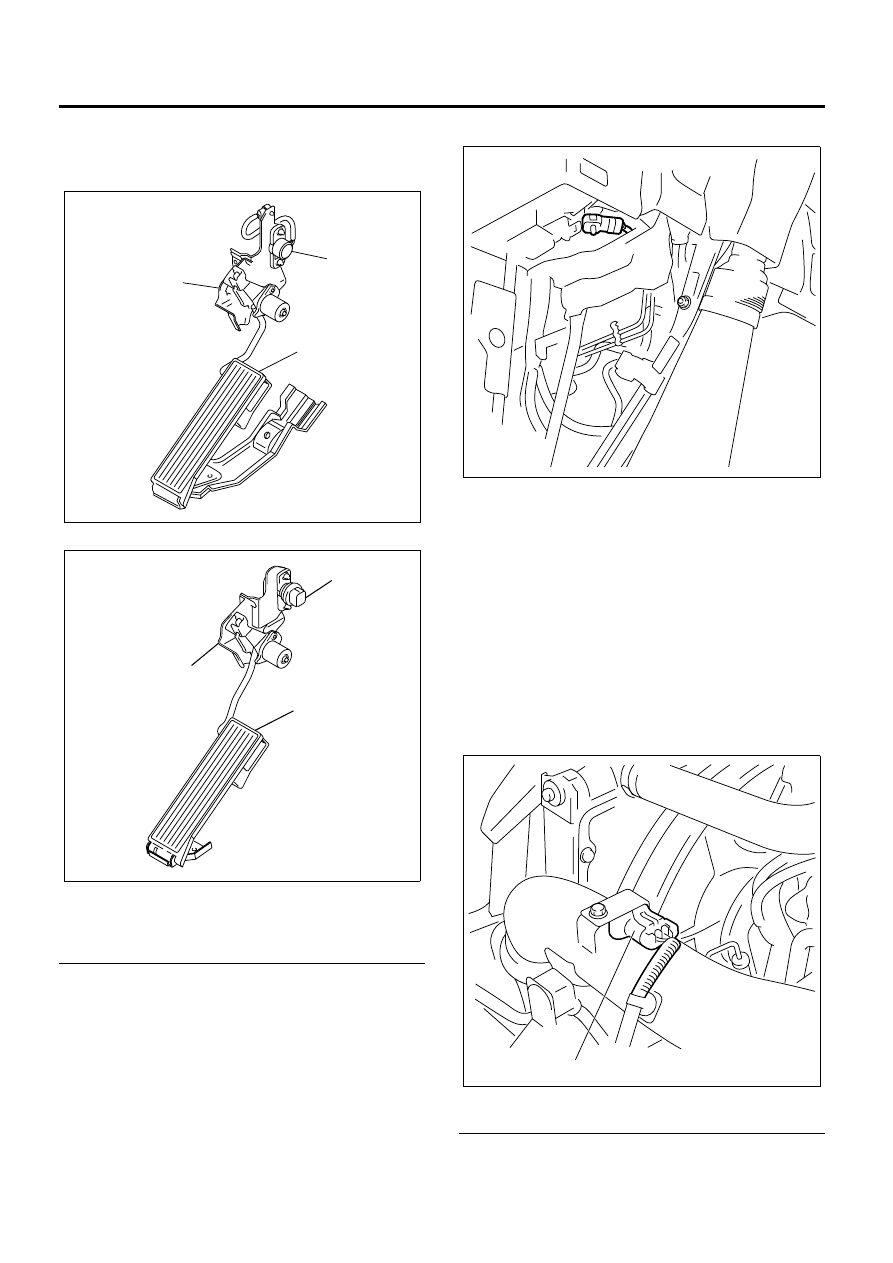
Accelerator Pedal Position (APP) Sensor
• LHD Model
• RHD Model
Legend
1. Control Link Bracket Assembly
2. Pedal Assembly
3. Accelerator Pedal Position (APP) Sensor
The accelerator pedal position (APP) sensor is
mounted on the control link bracket assembly. The
sensor is made up of two individual sensors within one
housing. The engine control module (ECM) uses the
APP sensor to determine the amount of acceleration or
deceleration desired by the person driving the vehicle
via the fuel injector control.
Barometric Pressure (BARO) Sensor
The barometric pressure (BARO) sensor is located
under the instrument panel cluster (IPC) near the pedal
bracket. The BARO sensor is a transducer that varies
voltage according to the barometric pressure changes
and the generated voltage is input to the engine control
module (ECM) for the BARO signal. The ECM should
detect a low signal voltage at a low barometric
pressure, such as high altitude place. The ECM should
detect high signal voltage at a high barometric
pressure. The ECM uses this voltage signal to calibrate
the fuel injection quantity and injection timing for
altitude compensation.
Boost Pressure Sensor
Legend
1. Boost Pressure Sensor
N6A6563E
3
1
2
N6A6566E
3
1
2
N6A6565E
N6A6569E
1