Isuzu N-Series. Manual - part 728


  Index      Isuzu     Isuzu N-Series - service repair manual


Search            


Content   ..  726  727  728  729   ..


Isuzu N-Series. Manual - part 728


6E-334    Engine Control System (4HK1) 
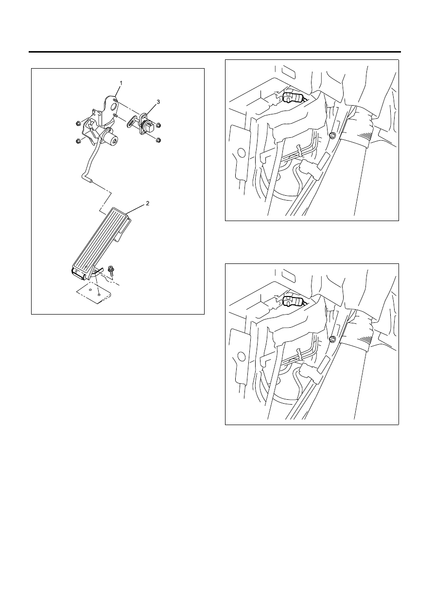
• RHD Model

1. Install the APP sensor (3) on the control link

bracket assembly (1).

2. Connect the APP sensor (3) connector.
3. Install the pedal assembly (2).
4. Install the control link bracket assembly (1).
5. Connect the nagative battery cable.

Barometric Pressure (BARO) Sensor
Replacement

Removal Procedure

1. Turn off the ignition.
2. Disconnect the negative battery cable.
3. Disconnect the barometric pressure (BARO)

sensor connector that is located under the
instrument panel cluster (IPC).

4. Remove the BARO sensor.

Installation Procedure

1. Install the BARO sensor on the installation bracket.

2. Connect the BARO sensor connector.
3. Connect the nagative battery cable. 

Boost Pressure Sensor Replacement

Removal Procedure

1. Turn off the ignition.
2. Loosen the boost pressure sensor bolt (2).
3. Disconnect the boost pressure sensor connector.
4. Remove the boost pressure sensor (1).

N6A6562E

N6A6565E

N6A6565E

 Engine Control System (4HK1)    6E-335

Installation Procedure

1. Install the boost pressure sensor (1).
2. Tighten the boost pressure sensor bolt (2).

Tighten:
Bolt to 8 N

⋅m (0.8 kg⋅m / 69 lb⋅in)

3. Connect the boost pressure sensor connector.

Camshaft Position (CMP) Sensor
Replacement

Removal Procedure

1. Turn off the ignition.
2. Loosen the camshaft position (CMP) sensor

retaining bolt.

3. Remove the CMP sensor.

Installation Procedure

1. Install the CMP sensor.

• Apply engine oil over the O-ring nice and thin

and install it.

2. Tighten the CMP sensor retaining bolt.

Tighten:
Bolt to 8 N

⋅m (0.8 kg⋅m / 69 lb⋅in)

Crankshaft Position (CKP) Sensor
Replacement

Removal Procedure

1. Disconnect the negative battery cable.
2. Loosen the crankshaft position (CKP) sensor

retaining bolt.

N6A6570E

1

2

N6A6570E

1

2

N6A6180E

N6A6180E

6E-336    Engine Control System (4HK1) 

3. Remove the CKP sensor.

Installation Procedure

1. Install the CKP sensor.
2. Tighten the CKP sensor retaining bolt.

Tighten:
Bolt to 8 N

⋅m (0.8 kg⋅m / 69 lb⋅in)

EGR Valve Replacement

Removal Procedure

1. Drain engine coolant. Refer to Engine Cooling

System section.

2. Remove the EGR valve connector.
3. Remove the EGR pipe.

Legend

1. EGR Adapter
2. Water Return Pipe
3. EGR Cooler
4. EGR Pipe
5. Water Feed Pipe


4. Remove the cooling water pipes.
5. Remove the EGR adapter.
6. Remove the EGR cooler.
7. Remove the EGR valve.

Caution:
After removing the EGR valve and EGR adapter, seal
the opening so that foreign matter does not enter.

Inspection Procedure

• Gas leak check

- Check for gas leak in various parts of the EGR

gas line.

N6A6056E

N6A6056E

N6A6025E

N6A6491E

 Engine Control System (4HK1)    6E-337

If the results of the check show abnormalities,
repair or replace the defective parts.

• EGR valve check

Installation Procedure

1. Mount the EGR valve.

• Insert the gasket and temporarily fit the EGR

valve.

Notice:
Temporarily tighten the bolts.

2. Install the EGR cooler.

• Temporarily fit the EGR cooler to the bracket.

Notice:
Temporarily tighten the bolts.

3. Install the EGR adapter.

• Temporarily fit the EGR adapter between the

EGR cooler and exhaust manifold.

Notice:
Temporarily tighten the bolts.

4. Install the EGR pipe.

• Insert the gasket between the two ends of the

EGR pipe and temporarily fit it.

Notice:
Temporarily tighten the bolts.

During temporary assembly, tighten the nuts
and bolts to the specified torque in the order
shown in the illustration.

Legend


Tighten:
1 : 31 N

⋅m (3.2 kg⋅m / 23 lb⋅ft)

2, 4 : 28 N

⋅m (2.9 kg⋅m / 21 lb⋅ft)

3, 5, 6, 7, 8, 9 : 24 N

⋅m (2.4 kg⋅m / 17 lb⋅ft)

Engine Coolant Temperature (ECT) Sensor
Replacement

Removal Procedure

1. Turn off the ignition.
2. Disconnect the engine coolant temperature (ECT)

sensor connector.

3. Remove the ECT sensor (1).

1 ~ 9 Show The Order of Tighten Bolts and Nuts.

N6A6522E


Content   ..  726  727  728  729   ..