Isuzu N-Series. Manual - part 657
6E-50 Engine Control System (4HK1)
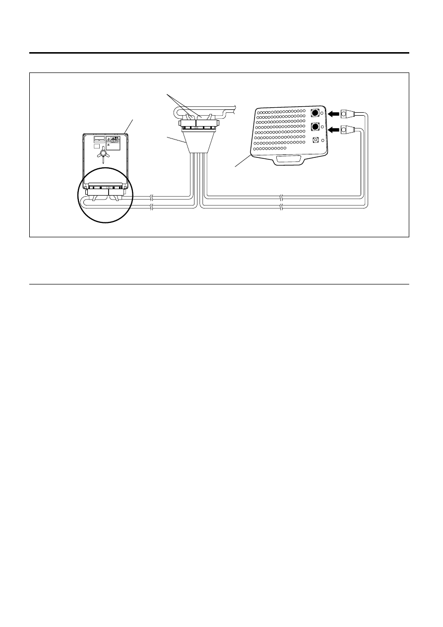
Breaker Box Connection Type B
Legend
1. Engine Control Module (ECM)
2. Adapter Harness
3. ECM – Harness Connector
4. Breaker Box
5. ECM connected
The ECM and other connectors have water proof
terminal that is not allowed to back probe. Breaker Box
Connection Type B is suitable usage to test short to
voltage circuit or signal check between the ECM and
electrical components.
CAUTION
To avoid electric shock;
Set the key switch to the "OFF" or "LOCK"
position before checking or repairing the
computer, wiring or/and connectors.
1
2
4
5
3
N6A6475E