Isuzu N-Series. Manual - part 643
TURBOCHARGER 6G-5
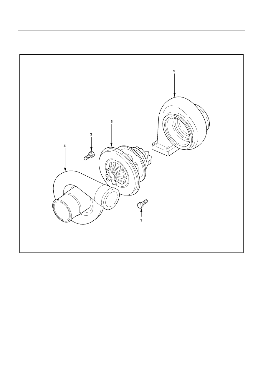
DISASSEMBLY
Component
Legend
1. Bolt
4. Compressor housing
2. Turbine housing
5. Center housing and rotating assembly
3. Bolt
N6A3603E
|
|
|
TURBOCHARGER 6G-5 DISASSEMBLY Component Legend 1. Bolt 4. Compressor housing 2. Turbine housing 5. Center housing and rotating assembly 3. Bolt N6A3603E |