Isuzu N-Series. Manual - part 628


  Index      Isuzu     Isuzu N-Series - service repair manual


Search            


Content   ..  626  627  628  629   ..


Isuzu N-Series. Manual - part 628


ENGINE ELECTRICAL 6D-5

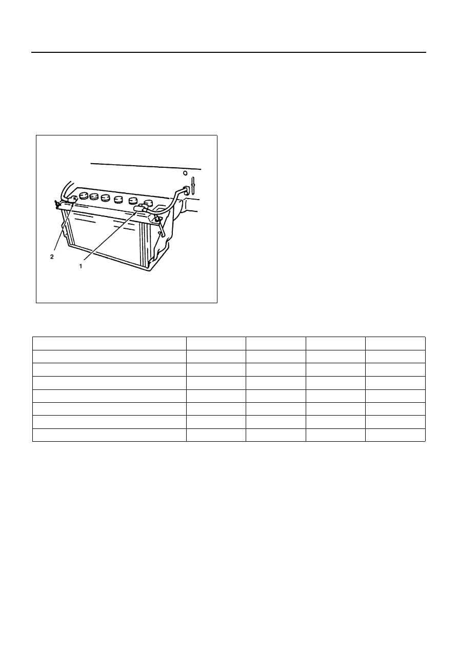
Removal and Installation of the Battery

Removal

1. All switches should be in the “OFF” position.
2. Disconnect the battery ground cable. (1)
3. Disconnect the battery positive cable. (2)
4. Disconnect the battery cable.

Caution:
It is important that the battery ground cable be discon-
nected first.
Disconnecting the battery positive cable first can result
in a short circuit.

Installation

To install the battery, follow the removal procedure in
the reverse order, noting the following points:

1. Make sure that the rod is hooked on the body side.

Main Data and Specifications

N6A3488E

Model

(JIS)

115E41R-MF

130E41R-MF

95D31R-MF

80D26R-MF

Voltage

(V)

12

12

12

12

Cold-Cranking Performance

(Amp)

651

799

622

582

Reserve Capacity

(Min)

212

229

159

133

Load Test

(Amp)

325

400

310

290

Fast Charge Maximum Amperage

(Amp)

20

20

20

20

BCI Group No.

27

24

Overall Dimension L

×W×H

(mm)

410

×178×213

410

×178×213

6D-6 ENGINE ELECTRICAL

STARTING SYSTEM

General Description

Starting Circuit

The cranking system consists of a battery, starter, starter switch, starter relay, etc. and these main components are
connected as shown in Figure. For details of the starting circuit.

Starter

The starting system employs a magnetic type reduction starter in which the motor shaft is also used as a pinion shaft.
When the starter switch is turned on, the contacts of magnetic switch are closed, and the armature rotates.
At the same time, the plunger is attracted, and the pinion is pushed forward by the shift lever to mesh with ring gear.
Then, the ring gear runs to start the engine. When the engine starts and the starter switch is turned off, the plunger
returns, the pinion is disengaged from ring gear, and the armature stops rotation. When the engine speed is higher
than the pinion, the pinion idles, so that the armature is not driven.

Legend

1. Starter motor

7. Relay; starter

2. Hold coil

8. “50” terminal

3. Contacts

9. “30” terminal

4. Pinion clutch

10. Battery

5. Pull in coil

11. Starter switch

6. Mognetic switch

N6A3489E

ENGINE ELECTRICAL 6D-7

Starting Circuit
For 4JB1, 4JB1-TC

N6A3490E

6D-8 ENGINE ELECTRICAL

Starting Circuit
For 4JH1

N6A3796E


Content   ..  626  627  628  629   ..