Isuzu N-Series. Manual - part 626


  Index      Isuzu     Isuzu N-Series - service repair manual


Search            


Content   ..  624  625  626  627   ..


Isuzu N-Series. Manual - part 626


6C-74 ENGINE FUEL

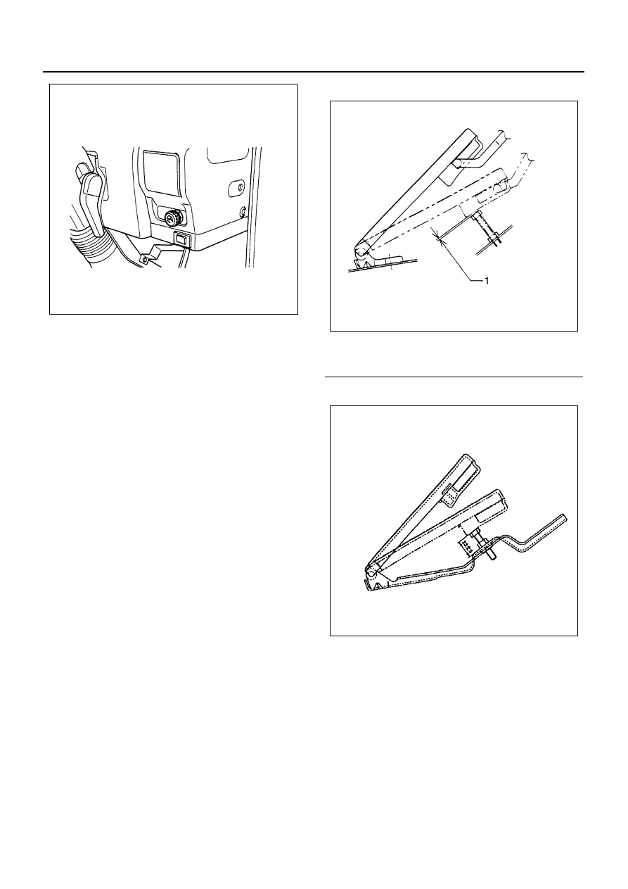
Adjustment of the Press-Down Amount of the Accel-
erator Pedal

• After installing each cable, give a full stroke to the

accelerator pedal while pushing the accelerator
pedal pad by hand.

• Adjust the stopper bolt so that the clearance be-

tween the pedal pad stopper bolt and the back of
the pad becomes 0 — 2 mm (0 — 0.079 in), and
tighten the lock nut to the specified torque.

Tighten:
7.4 N

⋅m(0.75 kg⋅m/65 lb⋅ft)

• Check to see if the accelerator pedal play is in the

range of 5 — 10 mm (0.2 — 0.4 in) above the pedal
pad.

• Press down on the accelerator pedal fully, and

check to see if the engine rotates at the maximum
speed with the linkage in the smooth operation.

• In the operating range of the accelerator pedal,

check to see if the accelerator pedal and the injec-
tion pump lever return without fail to their original
positions respectively.

RHD

LHD

N6A3475E

Legend

1. Full stroke 0 — 2 mm

N6A3478E

N6A3479E

ENGINE FUEL 6C-75

IDLING CONTROL CABLE

Component

Removal

1. Idling Control Knob

• Loosen the idling control knob screw and remove

the knob from cable.

2. Idling Control Cable Nut
3. Wave Washer
4. Idling Control Cable

• Remove control cable from accelerator pedal

bracket.

Inspection

• With the idling control knob not in use, check to see

if the injection pump lever is at the idle position
(with the lever in contact with the stopper bolt).

• With the idling control knob turned fully to the right,

check to see if the engine idles up to 1,500 rpm or
more.

Installation

1. Idling Control Cable

• Install control cable to accelerator pedal bracket.

2. Wave Washer
3. Idling Control Cable Nut

• Insert the idling control cable into the specified hole

of the instrument panel.

• Install the washer to the cable, and tighten it with

the nut.

4. Idling Control Knob

• Insert the idling control knob into the cable, and

tighten the screw.

Legend

1. Idling control knob

5. Wire guide

2. Idling control cable nut

6. Accelerator pedal bracket

3. Wave washer

7. Screw

4. Idling control cable

N6A3480E

6C-76 ENGINE FUEL

AIR CLEANER ELEMENT

Component

Removal

1. Cover Wing Nut
2. End Cover
3. Filter Wing Nut
4. Air Cleaner Element

Clean

• Wipe out the inside of the air cleaner assembly.
• Wipe off the cover.

Inspection

• The air filter with a light for fears or holes.

Legend

1. Cover wing nut

3. Filter wing nut

2. End cover

4. Air cleaner element

N6A3481E

N6A3482E

ENGINE FUEL 6C-77

Cleaning Method
Dust Fouled Element
Rotate the element with your hand while applying com-
pressed air to the inside of the element. This will blow
the dust free.

Caution:
Do not bang the element against another object in an at-
tempt to clean it. Damage to the element will result.

Carbon and Dust Fouled Element

1. Prepare a cleaning solution of Isuzu Genuine Ele-

ment Cleaner (Donaldson D1400) diluted with wa-
ter.

2. Submerge the element in the solution for twenty

minutes.

3. Remove the element from the solution and rinse it

well with running water.
Water pressure must not exceed 274 Kpa (2.8 kg/
cm

2

 /40 psi).

4. Dry the element in a well ventilated area. 

An electric fan will hasten drying.

Notice:
Do not use compressed air or an open flame to dry the
element quickly. Damage to the element will result. It will
usually take two or three days for the element to dry
completely. Therefore, it is a good idea to have a spare
on hand to use in the interim.

Installation

1. Air Cleaner Element
2. Filter Wing Nut
3. End Cover
4. Cover Wing Nut

Compressed air pressure

kPa (kg/cm

2

 /psi)

392 — 490 (4 — 5/57 — 71)

N6A0009E

N6A0010E

N6A0011E

N6A0012E


Content   ..  624  625  626  627   ..