Isuzu N-Series. Manual - part 625
6C-70 ENGINE FUEL
FUEL GAUGE UNIT
Component
Removal
Preparation:
• Disconnect battery ground cable.
1. Fuel Gauge Unit Connector
• Disconnect fuel gauge unit connector from fuel
gauge unit.
2. Fuel Gauge Unit
• Remove fuel gauge unit fixing screw and fuel
gauge unit.
Notice:
• After removing fuel gauge unit, cover fuel tank with
waste to prevent any dust entering.
Installation
1. Fuel Gauge Unit
2. Fuel Gauge Unit Connector
• Connect the wiring connector to the fuel gauge
unit.
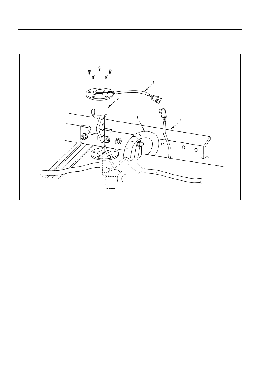
Legend
1. Fuel gauge unit connector
3. Evaporator fuel hose
2. Fuel gauge unit
4. Frame
N6A3473E