Isuzu N-Series. Manual - part 620
6C-50 ENGINE FUEL
• Install the Power Steering pump & bracket assem-
bly.
Tighten:
• 10M bolts to 40 N
⋅m (4.1 kg⋅m/30 lb⋅ft)
• 8M bolts to 19 N
⋅m (1.9 kg⋅m/14 lb⋅ft)
• Lock nut to 27 N
⋅m (2.8 kg⋅m/20 lb⋅ft)
15. AC Generator Drive Belt
• Install AC generator drive belt and adjust belt ten-
sion.
• Depress the drive belt mid-portion with a 98N (10
kg/ 22 lb) force.
• Install fixing bolt and tighten bolts to the specified
torque.
Tighten:
• Generator fixing bolt to 40 N
⋅m (4.1 kg⋅m/30 lb⋅ft)
• Adjust Plate Fixing Bolt to 19 N
⋅m (1.9 kg⋅m/14 lb⋅ft)
16. A/C Compressor Drive Belt (A/C Model)
• Install A/C compressor drive belt and adjust belt
tension.
• Depress the drive belt mid-portion with a 98N (10
kg/22lb) force.
• Tighten the Idler lock nut to the specified torque.
Tighten:
Idler lock nut to 27 N
⋅m (2.8 kg⋅m/ 20 lb⋅ft)
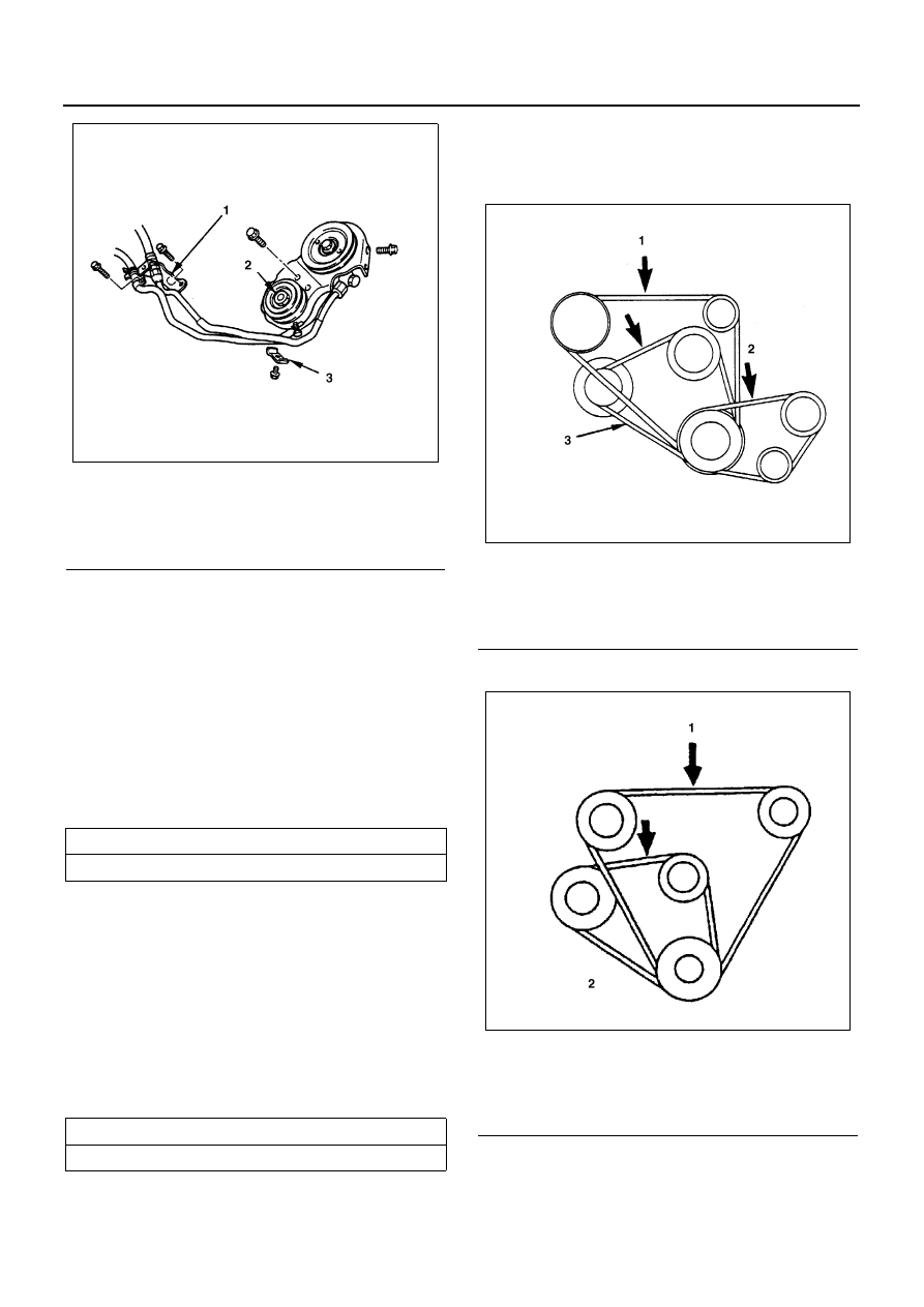
4JG2
4JB1
17. Power Steering Pump Drive Belt (P/S Model)
• Install power steering pump drive belt and adjust
belt tension.
Legend
1. Pipe bracket
2. Lock nut
3. Clip
Drive Belt Deflection
mm (in)
8 (0.31) — 12 (0.47)
Drive Belt Deflection
mm (in)
8 (0.31) — 12 (0.47)
N6A3793E
Legend
1. A/C compressor drive belt
2. P/S oil pump drive belt
3. AC generator fan pulley drive belt
Legend
1. A/C compressor drive belt & P/S pump drive
belt
2. AC generator & fan pulley drive belt
N6A3297E
N6A3295E