Isuzu N-Series. Manual - part 588


  Index      Isuzu     Isuzu N-Series - service repair manual


Search            


Content   ..  586  587  588  589   ..


Isuzu N-Series. Manual - part 588


6A1-40 4JB1/4JB1-TC/4JG2/4JH1-TC - ENGINE

2. Heater Hose

• Disconnect heater hose from heater pipe.

3. A/C Compressor Drive Belt

• Loosen idler lock nut.
• Loosen adjust bolt and remove drive belt.
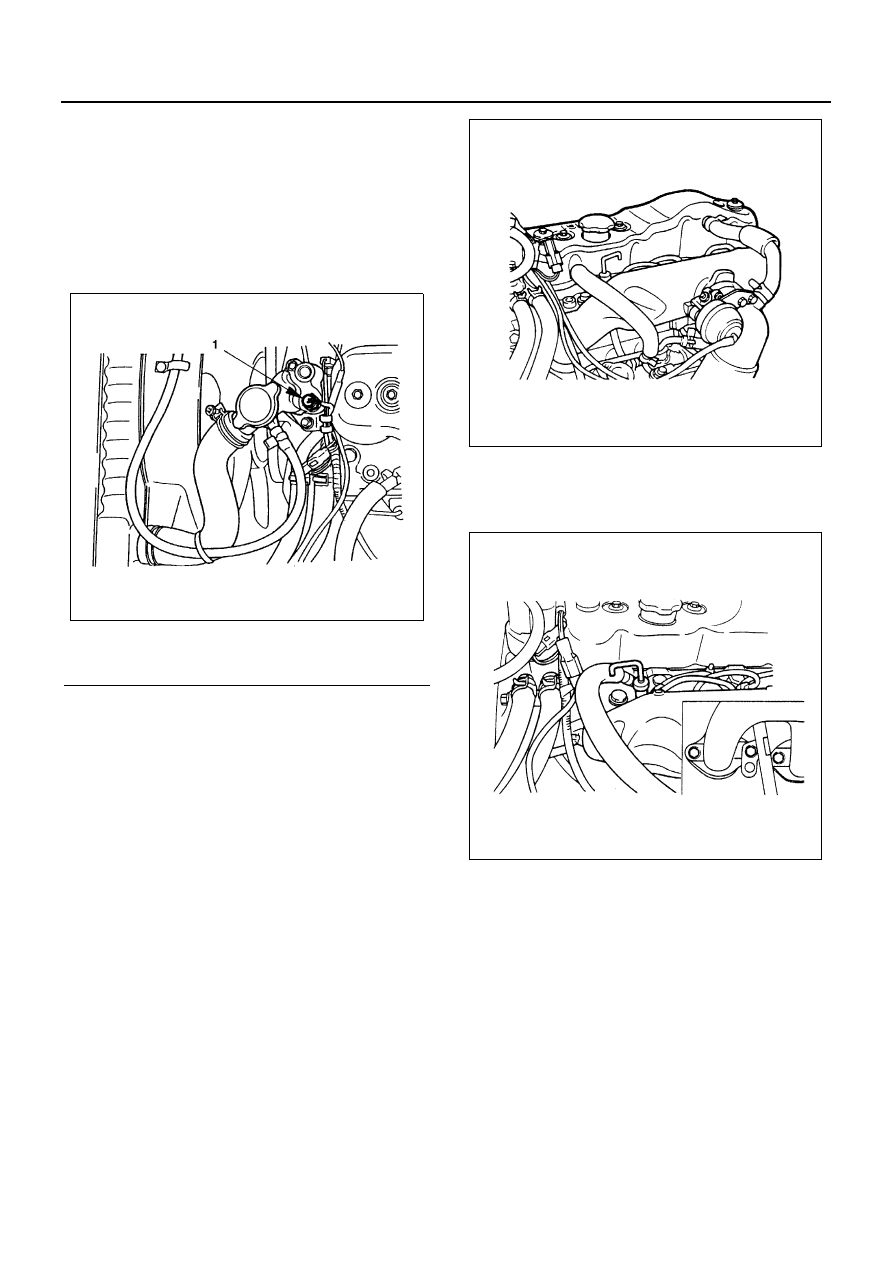
4. Engine Harness

• Disconnect harness connectors from units on ther-

mostat housing.

5. Air Intake Duct

• Remove the clip and air intake duct.

6. Injection Pipe

• Release injection pipe clip.
• Remove flare nut injection pump side.
• Remove flare nut injection nozzle side and remove

injection pipe.

Notice:
Plug the injection nozzle holder and the delivery holder
to prevent the entry of foreign matters into them.

7. Leak Off Pipe

• Remove the leak off pipe side of leak off hose.

8. PCV Hose

• Remove the PCV hose from air intake pipe.

9. Glow Plug Harness

10. Oil Level Gauge Guide Tube

• Remove the guide tube from cylinder head.

11. Oil Cooler Water Pipe (Oil Cooler Model)

• Remove the pipe fixing bolt of cylinder head rear

side.

• Remove the oil cooler water pipe fixing nut from in-

let manifold.

Legend

1. Thermo-sensor

N6A3286E

N6A3287E

N6A3288E

4JB1/4JB1-TC/4JG2/4JH1-TC - ENGINE 6A1-41

12. A/C Compressor Assembly (A/C Model)

• Remove the clutch harness connector.
• Remove the A/C compressor fixing bolts and tem-

porally tighten the A/C compressor to chassis
frame side use the wire.

13. Vacuum Actuator Hose (Exhaust Brake Model)

• Remove the vacuum hoses from vacuum actuator.

14. Front Exhaust Pipe

• Remove the exhaust pipe fixing bolts from exhaust

manifold.

• Remove the exhaust pipe stay bolt.

15. By-pass Hose
16. Cylinder Head Cover

17. Rocker Arm Shaft

• Loosen the rocker arm shaft bracket bolts a little at

a time in the numerical order shown in the illustra-
tion.

N6A3289E

N6A3290E

N6A3291E

N6A3292E

6A1-42 4JB1/4JB1-TC/4JG2/4JH1-TC - ENGINE

Notice:
Failure to loosen the rocker arm shaft bracket bolts a lit-
tle at a time in numerical order will adversely effect the
rocker arm shaft.

18. Push Rod
19. Cylinder Head Assembly

• Loosen the cylinder head bolts a little at a time in

the numerical order shown in the illustration.

Notice:
Failure to loosen the cylinder head bolts a little at a time
in numerical order will adversely effect the cylinder head
lower surface.

20. Cylinder Head gasket

• Remove the cylinder head gasket and dowel.

Installation

1. Cylinder Head Gasket

Cylinder head gasket is determined by the piston
head projection from the cylinder body upper sur-
face, in order to improve engine performance.
Three types of gasket are provided by the differ-
ence of thickness. Select the adequate one out of
three grades of gasket, according to the following
procedure.
Before measurement, clear off carbon from the pis-
ton head and cylinder body surface and also clean
the place where a gasket was installed.

Piston Head Projection Measurement Point

1) Use a dial indicator to measure the piston pro-

jection amount.

2) Refer to the illustration for the piston head pro-

jection measuring positions.
All measuring positions should be as close as
possible to the cylinder liner.

N6A3246E

N6A3055E

N6A3214E

N6A3215E

4JB1/4JB1-TC/4JG2/4JH1-TC - ENGINE 6A1-43

3) Measure the points (1), (2), (3) and (4) and ob-

tain two differences (1) — (2) and (3) — (4) on
each cylinder.
Calculate the average value of the piston head
projection on each cylinder.

4) Obtain the maximum value in the four cylinders.
5) Determine the gasket grade required to the

maximum value described above in accor-
dance with the following table.

4JB1

Notice:
The difference between the highest measured piston
head projection and the lowest measured piston head
projection must not exceed 1.0 mm (0.039 in).

4JG2

N6A3690E

N6A3216E

Legend

1. Grade mark

N6A3693E

N6A3217E


Content   ..  586  587  588  589   ..